Cowl-top cover

a technology of top cover and bottom plate, which is applied in the direction of superstructure subunits, vehicle components, pedestrian/occupant safety arrangements, etc., can solve the problems of comparatively high related rigidity and difficult longitudinal positioning of the terminal portion, and achieve the effect of easy deformation, and easy deformation and removal

Active Publication Date: 2016-04-19
NIHON PLAST CO LTD
View PDF6 Cites 0 Cited by
  • Summary
  • Abstract
  • Description
  • Claims
  • Application Information

AI Technical Summary

Benefits of technology

[0009]It is an object of the present invention to provide a cowl-top cover which is caused to be easily mountable to and removable from a vehicle body.
[0012]a low rigidity portion which is provided at such one end part of the cover main body portion in the longitudinal direction, the low rigidity portion being caused to be easily deformable so as to space the engagement portion in a counter-insertion direction with respect to the engagement receptacle portion.
[0019]In so far as the cowl-top cover according to the first aspect of the present invention is concerned, an engagement portion provided along a longitudinal direction from one end part in a longitudinal direction of a cover main body portion is inserted into and then engaged with an engagement receptacle portion which is disposed at an edge part of a wind shield in a direction crossing a face of this wind shield. In this manner, the cowl-top cover is caused to be easily mountable to a vehicle body. In addition, by way of a low rigidity portion which is provided at one end part in the longitudinal direction of the cover main body portion, the engagement portion is caused to be easily deformable from the engagement receptacle portion at such one end part in the longitudinal direction of the cover main body portion. Therefore, while the engagement portion that is removed from such one end part in the longitudinal direction of this cover main body portion is defined as a start point, this engagement portion is caused to be continuously removable from the engagement receptacle portion along the longitudinal direction of the cover main body portion, and the cowl-top cover is caused to be easily removable from the vehicle body.
[0020]In so far as the cowl-top cover according to the second aspect of the present invention is concerned, among a plurality of divisional members configured to divide a main body portion into a plurality of sections, an opening portion formed by cutting out a protrusion portion at one end part in a longitudinal direction is provided at one divisional member (a first divisional member). Thus, the other divisional member (a second divisional member) that is mounted to this opening portion is caused to be easily deformable and removable from the opening portion, whereby a position in proximity to the opening portion of such one divisional member can be determined as a low rigidity portion which is easily deformable. In this manner, by way of this low rigidity portion, the engagement portion of such one divisional member is caused to be easily deformable so as to space the engagement portion of such one divisional member in a counter-insertion direction with respect to the engagement receptacle portion, the engagement portion is caused to be easily removable from the engagement receptacle portion, and the cowl-top cover is caused to be more easily removable from the vehicle body.
[0021]In so far as the cowl-top cover according to the third aspect of the present invention is concerned, the other divisional member (the second divisional member) is detachable from an opening portion of such one divisional member (the first divisional member). Thus, the other divisional member is removed from an opening portion, whereby a position in proximity to an opening portion of such one divisional member can be determined as a low rigidity portion which is easily deformable. In this manner, by way of this low rigidity portion, an engagement portion of such one divisional member is caused to be easily deformable so as to space an engagement portion of such one divisional member in a counter-insertion direction with respect to the engagement receptacle portion, the engagement portion is caused to be easily removable from the engagement receptacle portion, and the cowl-top cover is caused to be more easily removable from the vehicle body.
[0022]In so far as the cowl-top cover according to the fourth aspect of the present invention is concerned, the other divisional member (the second divisional member) is formed of a member which is softer in material than such one divisional member (the first divisional member); and therefore, a low rigidity portion can be easily constructed at a position in proximity to an opening portion.

Problems solved by technology

However, a current cowl-top cover is prone to increase a gap between a bonnet / hood and a vehicle body panel in order to improve a pedestrian protection performance, and in order to compensate for such a gap, there are provided: a protrusion portion configured to protrude to the bonnet / hood's side along a widthwise direction which of a vehicle is a longitudinal direction thereof; and a transverse wall which is positioned at a terminal portion; and therefore, its related rigidity is comparatively high, and it is not easy to set the terminal portion in the longitudinal direction as a start point for deforming and removing the cowl-top cover.

Method used


Image

  • Cowl-top cover
  • Cowl-top cover
  • Cowl-top cover

Examples


first embodiment

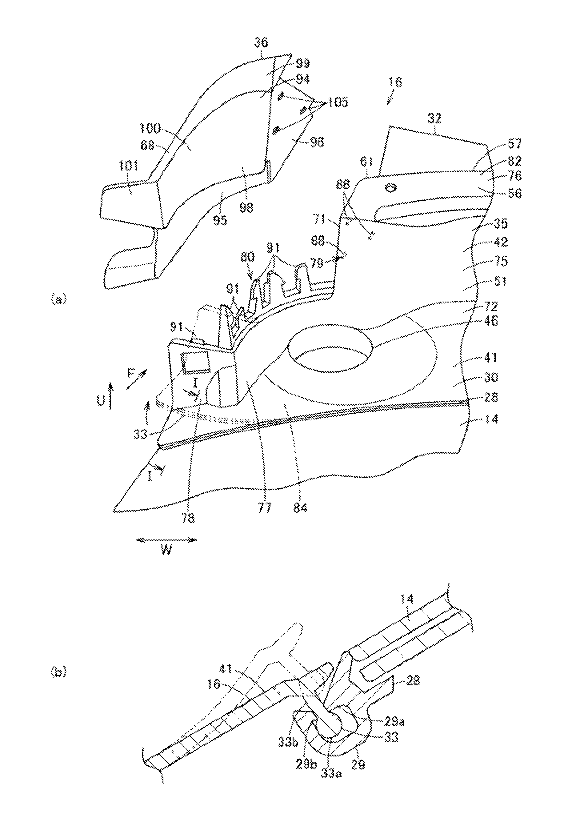
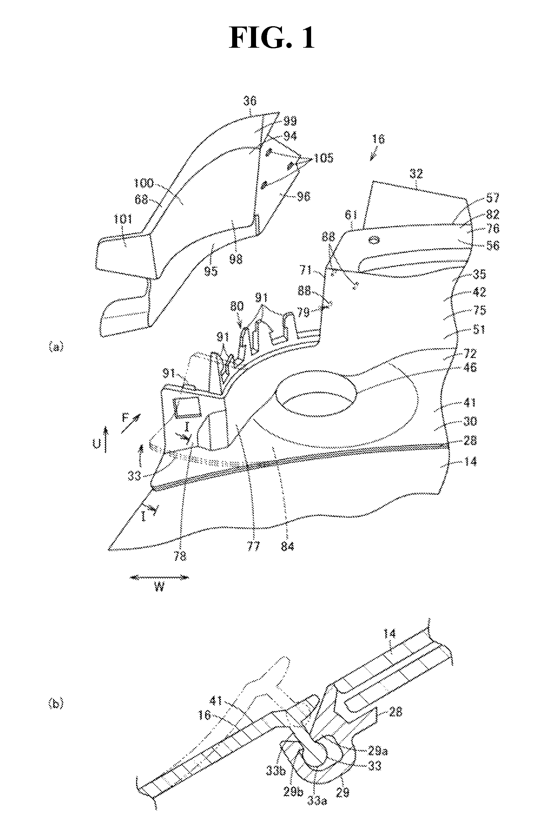
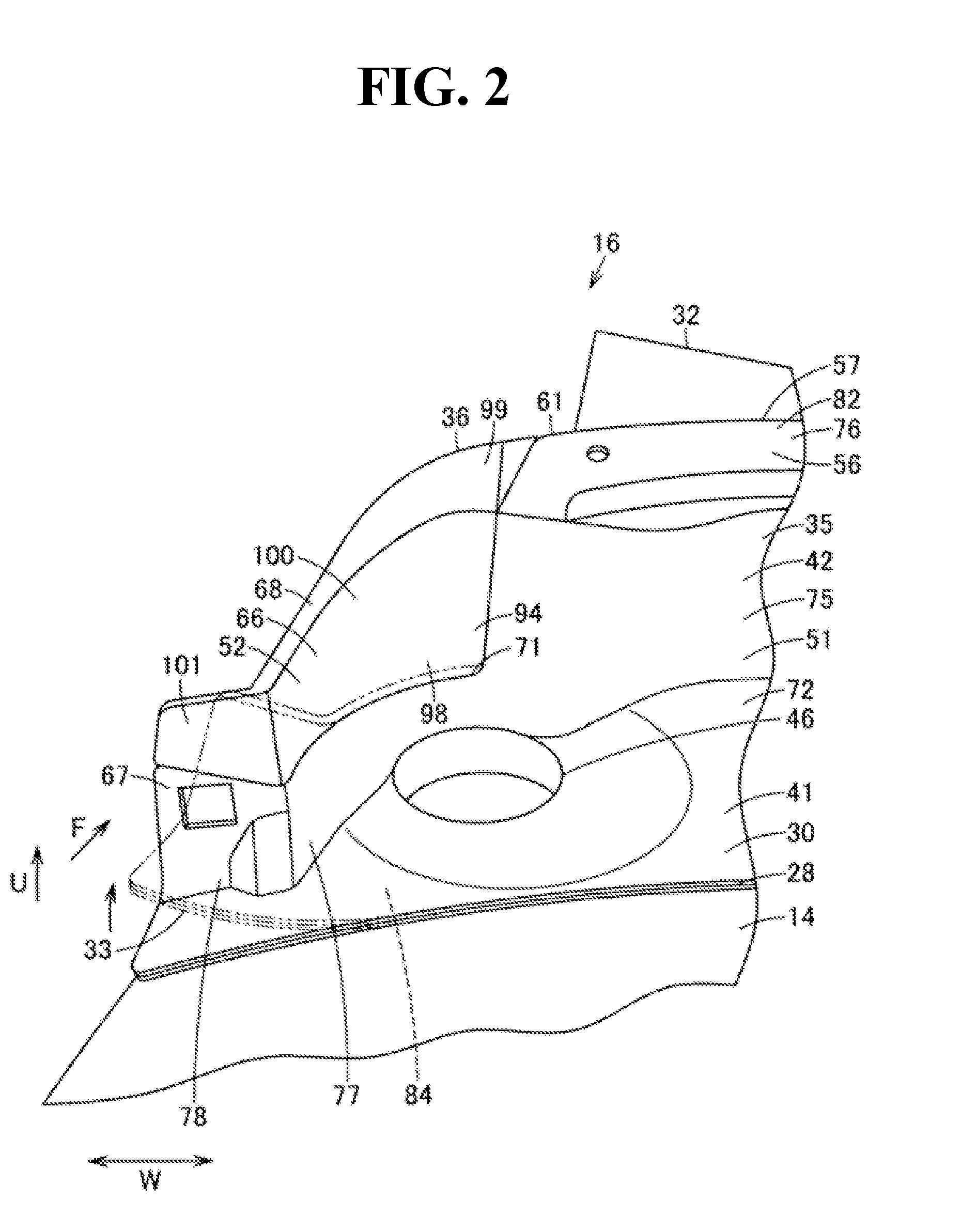
[0031]In FIG. 1 to FIG. 5, reference numeral 10 designates a vehicle body of a motor vehicle which is a vehicle, and in so far as this vehicle body 10 is concerned, a hood 12 serving as a counterpart member configured to cover an engine room 11; and a cowl-top cover 16 configured to cover a cowl portion 15 with respect to a front glass 14 serving as a wind shield which is positioned on a front side of a vehicle room 13, are mounted to the vehicle 10. Hereinafter, it is to be noted that, with respect to forward and backward, vertical, and lateral directions, a description will be given with respect to a cruising direction of the vehicle body 10, the direction indicated by the arrow F is defined as a forward direction, the direction indicated by the arrow U is defined as an upward direction, and the direction indicated by the arrow W is defined as a widthwise direction of a vehicle 10 which is a transverse direction.

[0032]Also, this cowl portion 15 is referred to as an air box or the ...

second embodiment

[0081]Next, a second embodiment will be described with reference to FIG. 6. It is to be noted that like constituent elements and functions of the first embodiment described above are designated by like reference numerals, and its related description is omitted.

[0082]According to the second embodiment, an opening portion 71 of a main body member 35 is cut out and formed in the shape of an elongated hole (in the shape of a slit) along a longitudinal direction at an end part in a longitudinal direction of a main body portion 31, and an auxiliary member 36 is detachable from this opening portion 71.

[0083]That is, the opening portion 71 is formed along a longitudinal direction of a cover main body portion 30 in proximity to a lower end part of a rear wall portion 67 of a transverse wall portion 52 of a reverse V-shaped portion 42, that is, along the proximity of a position which is continuous to a flat plate portion 41.

[0084]In addition, an auxiliary member 36 is integrally provided with...

third embodiment

[0088]Next, a third embodiment will be described with reference to FIG. 7. Although the main body member 35 according to a respective one of the first and second embodiment described above has been formed in the shape of one elongated substantial plate covering the cowl portion 15 all over the substantially widthwise direction of the vehicle 10, this main body portion is not limitative thereto, and may be formed so as to be divided into a plurality of main body members 35a, 35a such as two left and right members each having a length which is half of that in the substantially widthwise direction of the vehicle 10, for example, as is the case with the third embodiment as shown in FIG. 7. In this case, at least either one of abutment portions of the main body portions 35a, 35a that are adjacent to each other, for example, cutout portions 109, 109 which are respectively cut out are provided in the embodiment, and these cutout portions 109, 109 are configured to form the opening portion ...


PUM


Abstract

The present invention provides a cowl-top cover. A cover mounting portion which is provided along a longitudinal direction from one end part in a longitudinal direction of a cover main body portion is inserted into and then engaged with an engagement receptacle portion, whereby the cowl-top cover is caused to be easily mountable to a vehicle body. A low rigidity portion which is provided at one end part in the longitudinal direction of the cover main body portion is deformed so as to space the cover mounting portion in a counter-insertion direction with respect to the engagement receptacle portion, whereby the cover mounting portion is caused to be easily removable from the engagement receptacle portion at a position of one end part in the longitudinal direction of the cover main body portion.

Description

CROSS REFERENCE TO RELATED APPLICATIONS[0001]This application claims priority of Japanese Patent Application No. 2013-185110 filed on Sep. 6, 2013. The contents of this application are incorporated herein by reference in their entirety.BACKGROUND OF THE INVENTION[0002]1. Field of the Invention[0003]The present invention relates to a cowl-top cover provided with a cover main body portion disposed at an edge part of a wind shield, a widthwise direction of a vehicle is defined as a longitudinal direction thereof.[0004]2. Description of the Related Art[0005]Conventionally, there has been employed a cowl-top cover which is disposed at a so called cowl portion between a front end part of a front glass and a rear side part of a bonnet / hood, of a motor vehicle, and which covers this cowl portion to improve its related appearance. Such a cowl-top cover is provided with a plate-shaped cover main body portion configured to cover the cowl portion, a cover mounting portion which is formed at a r...

Claims


Application Information

Patent Timeline
Patent Type & Authority Patents(United States)
IPC IPC(8): B60R21/34B62D25/08
CPCB62D25/081B60R21/34B60R2021/343
Inventor HIRANO, MASANORI
Owner NIHON PLAST CO LTD
Why Eureka
Try Eureka