Cleaner head

Pending Publication Date: 2021-02-25
DYSON TECH LTD
View PDF0 Cites 0 Cited by
  • Summary
  • Abstract
  • Description
  • Claims
  • Application Information

AI Technical Summary

Benefits of technology

[0011]At least part of the perimeter edge of the seal may not be fixed to the housing, such that air is able to enter into and escape from the hollow seal. As a result, air isn't trapped with the seal, causing an increase in pressure as the seal is deformed. Therefore the seal is more easily deformable, and it is better able to conform to a surface being cleaned as the cleaner head travels over it, and a better seal can be achieved between the cleaner head and the surface being cleaned.
[0012]In an unbiased position the lower sealing surface may lie at an angle of between 10° and 45° from a plane defined by the sole plate, and may lie at an angle of between 20° and 35° from a plane defined by the sole plate. This lie angle range for the rear seal strikes a good balance of providing enough downwards

Problems solved by technology

This has the effect of reducing the pressure differe

Method used


Image

  • Cleaner head
  • Cleaner head
  • Cleaner head

Examples


Embodiment Construction

[0029]Directional terminology such as “front” and “rear” are used herein with respect to the forward and rearward stroke directions of the cleaner head during typical use. Similarly, “downward” means in a direction towards a floor surface on which the cleaner head is positioned during a typical cleaning operation.

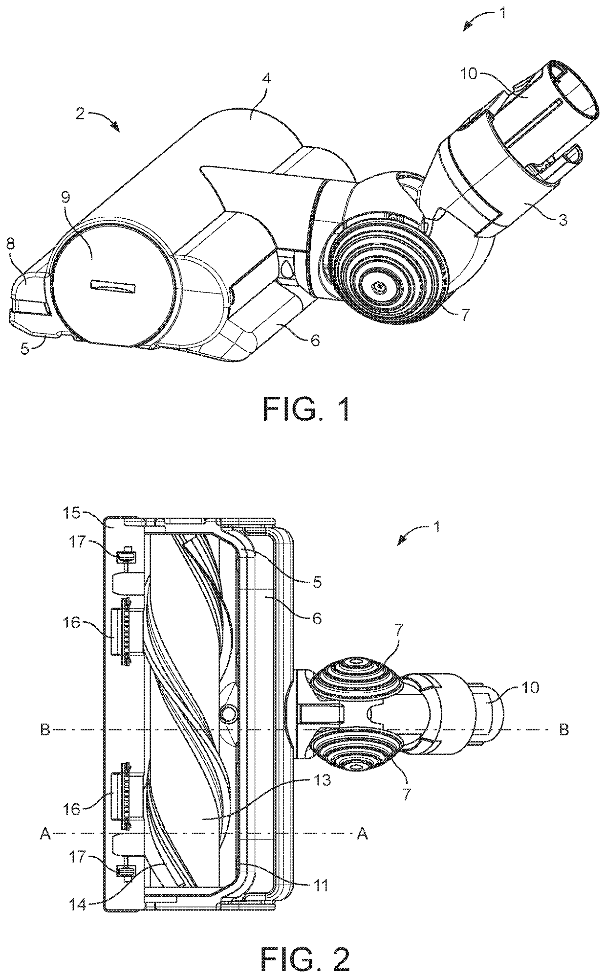
[0030]FIG. 1 shows a cleaner head 1 comprising a head portion 2 and an articulated neck 3 which is rotatably connected to the head portion 2. The head portion 2 comprises a sole plate 5, and a housing 4 which defines a suction chamber inside which a brushbar is housed. A rear seal 6 is located at the rear of the cleaner head such that it extends in a downward and rearward direction from the rear of the housing 4. At the front of the cleaner head 1 attached to the housing 4 is a front edge housing 8. The front edge housing 8 accommodates an actuating mechanism that will described in more detail later. A removable end cap 9 is provided on one side of the housing 4 which provi...


PUM


Abstract

A cleaner head for a cleaning appliance, the cleaner head comprising: a housing defining a suction chamber; and a sole plate defining a downwardly-directed opening through which dirt can enter the suction chamber. The cleaner head further comprises a hollow deformable seal extending from a rear portion of the housing, the hollow deformable seal having a width at least equal to a width of the opening in the sole plate, and having a lower sealing surface that extends in a downward and rearward direction from a rear edge of the housing such that, in use, the hollow deformable seal is biased against and conforms to a surface being cleaned in order to maintain a seal between the cleaner head and the surface being cleaned.

Description

REFERENCE TO RELATED APPLICATIONS[0001]This application is a national stage application under 35 USC 371 of International Application No. PCT / GB2019 / 050127, filed Jan. 17, 2019, which claims the priority of United Kingdom Application No. 1803285.4, filed Feb. 28, 2018, the entire contents of each of which are incorporated herein by reference.FIELD OF THE DISCLOSURE[0002]The present disclosure relates to a cleaner head, in particular a cleaner head for a vacuum cleaner.BACKGROUND OF THE DISCLOSURE[0003]There is a constant desire to improve the pickup performance of vacuum cleaners. The cleaner head of a vacuum cleaner plays an important role in the level of dirt pickup that can be achieved. There are a number of ways in which pickup performance can be improved, one of the most important of which is to maintain a decent pressure differential between the inside the cleaner head and the outside of the cleaner head.[0004]However, when a vacuum cleaner is being used, the cleaner head is m...

Claims


Application Information

Patent Timeline
IPC IPC(8): A47L9/06A47L9/04
CPCA47L9/0666A47L9/0466A47L9/04A47L9/02A47L9/06A47L9/066A47L9/0606
Inventor GENN, STUART LLOYDCOX, ROBERT MICHAELSTUBBS, MATTHEW JONATHAN
Owner DYSON TECH LTD
Why Eureka
Try Eureka