Manufacturing method of honeycomb structure

Inactive Publication Date: 2018-06-21
NGK INSULATORS LTD
3 Cites 0 Cited by

AI-Extracted Technical Summary

Problems solved by technology

This “honeycomb structure body having two types of cell structures” also has the problem that deformation or distortion occurs in the circumferential shape of the honeycomb formed body.
Consequently, it is remarkably difficult to correct a shape of the deformed honeycomb formed body (i.e., adjust the deformed shape) after the extrusion.
However, for the honeycomb formed body ...

Benefits of technology

[0006]In extrusion of a honeycomb formed body, there is a case where horizontal extrusion is employed in which an extruding direction is a horizontal direction, and there is another case where vertical extrusion is employed in which the extruding direction is a vertical direction (downward). In the case of forming the honeycomb formed body by the horizontal extrusion, it is necessary...

Abstract

A manufacturing method of a honeycomb structure include a forming step of extruding a kneaded material including a forming raw material by use of a horizontal forming machine include a forming die in which latticed slits are formed in a kneaded material discharge surface, to obtain a round pillar-shaped honeycomb formed body having latticed partition walls; and a firing step of firing the obtained honeycomb formed body to prepare the honeycomb structure. In the forming step, there is used the forming die in which there are formed the slits different in lattice shape between a central portion and a circumferential portion in the kneaded material discharge surface, and the forming die is disposed in an orientation in which an inclination of one row of the latticed slits formed in the central portion is within an angle of ±10° to a vertical direction, to extrude the kneaded material in a horizontal direction.

Application Domain

Ceramic extrusion diesCeramicware

Technology Topic

Image

  • Manufacturing method of honeycomb structure
  • Manufacturing method of honeycomb structure
  • Manufacturing method of honeycomb structure

Examples

  • Experimental program(2)

Example

Example 1
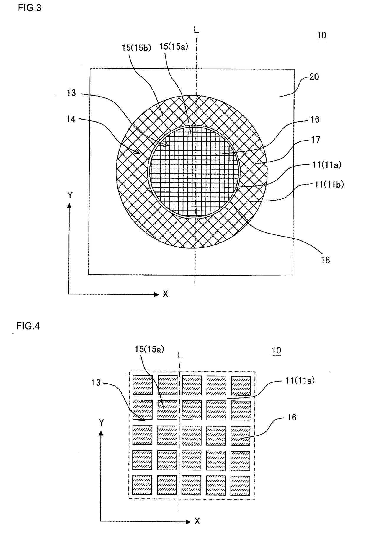
[0081]In Example 1, a honeycomb structure was manufactured by using a forming die 10 in which one row of latticed slits 11b formed in a circumferential portion 14 was inclined at 45° to one row of latticed slits 11a formed in a central portion 13 as shown in FIG. 3 and FIG. 4.
[0082]The honeycomb structure as a final product had a round pillar shape in which a diameter of each end face was 100 mm, and a diameter of a cell structure of a central portion in the end face was 70 mm. A boundary between the cell structure of the central portion and a cell structure of a circumferential portion had a boundary wall having a thickness of 0.1 mm. A value of a diameter of the cell structure of the above-mentioned central portion included this thickness of the boundary wall. In the cell structure of the central portion, a cell shape was quadrangular, a partition wall thickness was 0.09 mm, and a cell density was 93 cells/cm2. In the cell structure of the circumferential portion, a cell shape was quadrangular, a partition wall thickness was 0.11 mm, and a cell density was 62 cells/cm2. This honeycomb structure had the cell structure in which an arrangement direction of quadrangular cells of the central portion intersected an arrangement direction of cells of the circumferential portion at an angle of 45° in a cross section of the honeycomb structure which was perpendicular to an extending direction of the cells. The diameter of 100 mm of the end face of the honeycomb structure as the above-mentioned final product and the diameter of 70 mm of the cell structure of the central portion were defined as “standard values” in Example 1.
[0083]In Example 1, there was prepared the die in which the slits corresponding to the above-mentioned shape of the honeycomb structure were formed, extrusion was performed by using a kneaded material prepared by the following method, and an obtained honeycomb formed body was fired to manufacture the honeycomb structure. In Example 1, there were manufactured 200 honeycomb structures. In a forming step, the forming die was disposed in an orientation in which one row of latticed slits formed in the central portion of the forming die was parallel to a vertical direction, to extrude the kneaded material in a horizontal direction.
Preparing Method of Kneaded Material
[0084]The preparation of the kneaded material was performed by using a cordierite forming raw material as a forming raw material. Specifically, 5 parts by mass of a pore former, 85 parts by mass of a dispersing medium and 8 parts by mass of an organic binder were added to 100 parts by mass of the cordierite forming raw material, and mixed and kneaded to prepare the kneaded material. As the cordierite forming raw material, alumina, aluminum hydroxide, kaolin, talc and silica were used. Water was used as the dispersing medium, a water absorbable polymer having an average particle diameter of 100 to 105 μm was used as the pore former, methylcellulose was used as the organic binder, and 3 parts by mass of a surfactant was used as a dispersing agent.
[0085]In Example 1, as to the honeycomb formed body obtained by the extrusion, an outer diameter of the circumferential portion and an outer diameter of the central portion were measured in a measurement region mentioned below. Specifically, as to the honeycomb formed body obtained by the extrusion, there were measured the outer diameter of the circumferential portion and the outer diameter of the central portion in cross sections cut in three arrow directions D1, D2 and D3 shown in FIG. 12.
[0086]The outer diameter of the circumferential portion corresponded to an outer diameter of the honeycomb formed body, and the outer diameter of the central portion corresponded to an outer diameter of the boundary wall defining the circumferential portion and the central portion. In FIG. 12, D1 is a position of 1 mm from a second end face 36 of a honeycomb formed body 30. D2 is an intermediate point between the second end face 36 and a first end face 35 of the honeycomb formed body 30. D3 is a position of 1 mm from the first end face 35 of the honeycomb formed body 30. Furthermore, as to three cross sections cut in the three arrow directions denoted with D1, D2 and D3, respective dimensions were measured in four directions as shown in FIG. 13. Specifically, the respective dimensions were measured in the four directions of a vertical direction A, a horizontal direction B, a depression direction C from the horizontal direction toward the downside at an angle of 45° and an elevation direction D from the horizontal direction toward the upside at an angle of 45°. Table 1 shows the measurement results. The result shown in Table 1 is an average value of the measurement results of 20 honeycomb formed bodies. Table 1 shows, in a column of a “circumferential portion”, values of the outer diameters of the circumferential portions which were measured at measurement points of FIG. 12 and FIG. 13. Furthermore, Table 1 shows, in a column of a “central portion”, values of the outer diameters of the central portions which were measured at the measurement points of FIG. 12 and FIG. 13.
[0087]Here, FIG. 12 shows a schematic perspective view of the honeycomb formed body to explain the measurement region of the outer diameter of the circumferential portion and the outer diameter of the central portion in the honeycomb formed body. FIG. 13 is a cross-sectional view showing a cross section of the honeycomb formed body shown in FIG. 12 which is perpendicular to a cell extending direction.
[0088]Furthermore, there was calculated a difference between each of the outer diameter of the circumferential portion and the outer diameter of the central portion which were measured by the above-mentioned method and each standard value. Additionally, there were also calculated “a difference (mm) between a maximum value and an average value” and “a difference (mm) between the average value and a minimum value”. Table 1 shows the results. Furthermore, on the basis of the above results, there was prepared a graph showing dimensional differences from the standard values in the honeycomb formed body extruded in the manufacturing method of the honeycomb structure of Example 1. FIG. 16 shows the prepared graph. FIG. 16 is the graph showing the dimensional differences from the standard values in the honeycomb formed body extruded in the manufacturing method of the honeycomb structure of Example 1.
TABLE 1 Difference Difference Difference between between between average value maximum value average value and standard and average and minimum value value value Measurement region (mm) (mm) (mm) Circum- A D1 −1.09 1.1 0.9 ferential D2 −1.12 0.7 0.5 portion D3 −1.08 0.4 0.6 B D1 −0.835 1.2 1.1 D2 −0.78 0.7 0.5 D3 −0.86 0.4 0.6 C D1 −1.156 0.9 0.9 D2 −1.251 0.7 0.4 D3 −1.349 0.4 0.7 D D1 −1.135 1.1 0.9 D2 −1.206 0.5 0.5 D3 −1.139 0.4 0.6 Central A D1 0.445 0.4 0.8 portion — — — — D3 0.345 0.5 0.4 B D1 0.585 0.4 0.3 — — — — D3 0.485 0.4 0.6 C D1 0.68 0.5 0.4 — — — — D3 0.69 0.8 0.7 D D1 0.712 0.9 0.7 — — — — D3 0.514 0.8 0.5

Example

Comparative Example 1
[0089]In Comparative Example 1, a kneaded material prepared by a method similar to Example 1 was extruded by using such a forming die 110 as shown in FIG. 14 and FIG. 15 to prepare a honeycomb formed body. FIG. 14 is a front view schematically showing the forming die for use in a forming step of a manufacturing method of a honeycomb structure of Comparative Example 1. FIG. 15 is an enlarged front view in which a central portion of the forming die shown in FIG. 14 is enlarged.
[0090]The forming die 110 shown in FIG. 14 and FIG. 15 is constituted of a first die 116 and a second die 117. Latticed slits 111 are formed in kneaded material discharge surfaces 115 of the first die 116 and the second die 117, respectively. In the first die 116, a kneaded material discharge surface 115a possesses a round shape corresponding to a central portion of the honeycomb formed body, and in the second die 117, a kneaded material discharge surface 115b possesses a ring shape corresponding to a circumferential portion of the honeycomb formed body. In the forming die 110, quadrangular latticed slits 111a are formed in a central portion 113 of the first die 116, and quadrangular latticed slits 111b are also formed in a circumferential portion 114 consisting of the second die 117. In FIG. 14, reference numeral 118 denotes a clearance area to form a boundary wall defining the central portion and circumferential portion of the honeycomb formed body.
[0091]In a forming step of Comparative Example 1, as shown in FIG. 14 and FIG. 15, the forming die 110 was disposed so that one row of the latticed slits 111a formed in the central portion 113 of the forming die 110 was inclined at 45° to a vertical direction, to extrude the kneaded material in a horizontal direction. In this forming step, one row of the latticed slits 111b formed in the circumferential portion 114 of the forming die 110 was parallel to the vertical direction. In FIG. 14 and FIG. 15, one-dot chain lines denoted with symbols L′ and L″ indicate extending directions of one row of the quadrangular latticed slits 111a of the central portion 113 (i.e., an orientation of each row of the slits 111a of the central portion 113).
[0092]Also in Comparative Example 1, as to the honeycomb formed body obtained by the extrusion, an outer diameter of the circumferential portion and an outer diameter of the central portion were measured by a method similar to Example 1. Furthermore, there was calculated a difference between each of measured values of the outer diameter of the circumferential portion and the outer diameter of the central portion and each standard value. Furthermore, “a difference (mm) between a maximum value and an average value” and “a difference (mm) between the average value and a minimum value” were also calculated, respectively. Table 2 shows the results.
TABLE 2 Difference Difference Difference between between between average value maximum value average value and standard and average and minimum value value value Measurement region (mm) (mm) (mm) Circum- A D1 −1.88 1.3 0.7 ferential D2 −1.76 0.9 0.8 portion D3 −1.55 0.5 0.4 B D1 0.485 1.1 0.9 D2 0.495 0.8 0.5 D3 0.38 0.2 0.1 C D1 −1.115 1.1 0.8 D2 −0.995 0.4 0.5 D3 −1.065 0.4 0.6 D D1 −1.135 1.4 1.1 D2 −0.775 0.7 0.5 D3 −1.075 0.6 0.6 Central A D1 0.2 0.4 0.5 portion — D3 0.335 0.8 0.7 B D1 1.335 0.9 0.8 — D3 1.19 0.5 0.7 C D1 0.44 0.6 0.7 — D3 0.39 0.7 0.6 D D1 0.42 0.5 0.7 — D3 0.42 0.8 0.7
[0093]Furthermore, on the basis of the above results, there was prepared a graph showing dimensional differences from the standard values in the honeycomb formed body extruded in the manufacturing method of the honeycomb structure of Comparative Example 1. FIG. 17 shows the prepared graph. FIG. 17 is the graph showing the dimensional differences from the standard values in the honeycomb formed body extruded in the manufacturing method of the honeycomb structure of Comparative Example 1.
Result
[0094]In a honeycomb formed body extruded by a manufacturing method of a honeycomb structure of Example 1, “a difference between an average value and a standard value” indicated comparatively uniform values in four directions of a vertical direction A, a horizontal direction B, a depression direction C and an elevation direction D of FIG. 13. On the other hand, in a honeycomb formed body extruded by a manufacturing method of a honeycomb structure of Comparative Example 1, “a difference between an average value and a standard value” had a larger deviation than in Example 1. Furthermore, the honeycomb formed body extruded by the manufacturing method of the honeycomb structure of Example 1 also indicated comparatively uniform values in three cross sections cut in three arrow directions denoted with D1, D2 and D3 of FIG. 12. On the other hand, in the honeycomb formed body extruded by the manufacturing method of the honeycomb structure of Comparative Example 1, values in the above three cross sections also had larger deviations than in Example 1.
[0095]As seen from the above results, according to the manufacturing method of the honeycomb structure of Example 1, it was possible to manufacture a honeycomb structure having an excellent shape accuracy. Furthermore, in manufacturing methods other than the manufacturing method of Example 1, it has been confirmed that a difference between an average value and a standard value decreases in the same manner as in Example 1, when an inclination of one row of latticed slits formed in a central portion is within an angle of ±10° to a vertical direction.
[0096]A manufacturing method of a honeycomb structure of the present invention is utilizable as a method of manufacturing a honeycomb structure for use as an exhaust gas purifying filter or catalyst carrier.
DESCRIPTION OF REFERENCE NUMERALS
[0097]1: horizontal forming machine, 10, 60 and 110: forming die, 11, 61 and 111: slit, 11a, 61a and 111a: slit (slits of a central portion), 11b, 61b and 111b: slit (slits of a circumferential portion), 13, 63 and 113: central portion, 14, 64 and 114: circumferential portion, 15, 65 and 115: kneaded material discharge surface, 15a, 65a and 115a: kneaded material discharge surface (the kneaded material discharge surface of a first die), 15b, 65b and 115b: kneaded material discharge surface (the kneaded material discharge surface of a second die), 16, 66 and 116: first die, 17, 67 and 117: second die, 18, 68 and 118: clearance area (the clearance area to form a boundary wall), 19: back hole, 19b: second back hole, 20: space forming member, 21: pressing plate, 22: die holder, 23: cylinder of the horizontal forming machine, 25: receiving base, 26: support surface (the support surface of the receiving base), 27: conveyor, 30: honeycomb formed body, 31: partition wall, 31a: partition wall (partition walls of a central portion), 31b: partition wall (partition walls of a circumferential portion), 32: cell, 32a: cell (cells of the central portion), 32b: cell (cells of the circumferential portion), 33: central portion (the central portion of a honeycomb formed body), 34: circumferential portion (the circumferential portion of the honeycomb formed body), 35: first end face, 36: second end face, 40: kneaded material, 50: honeycomb structure, 51: partition wall, 51a: partition wall (partition walls of the central portion), 51b: partition wall (partition walls of the circumferential portion), 52: cell, 52a: cell (cells of the central portion), 52b: cell (cells of the circumferential portion), 53: central portion (the central portion of a honeycomb structure), 54: circumferential portion (the circumferential portion of the honeycomb structure), 55: first end face, 56: second end face, 57: circumferential wall, 58: boundary wall, L, L′ and L″: orientation of one row of the slits of the central portion, X: direction perpendicular to a vertical direction and an extruding direction, Y: vertical direction, and Z: extruding direction.

PUM

PropertyMeasurementUnit
Angle10.0°
Angle20.0 ~ 55.0°
Fraction0.6 ~ 0.8fraction
tensileMPa
Particle sizePa
strength10

Description & Claims & Application Information

We can also present the details of the Description, Claims and Application information to help users get a comprehensive understanding of the technical details of the patent, such as background art, summary of invention, brief description of drawings, description of embodiments, and other original content. On the other hand, users can also determine the specific scope of protection of the technology through the list of claims; as well as understand the changes in the life cycle of the technology with the presentation of the patent timeline. Login to view more.

Similar technology patents

Workpiece support device

InactiveUS20060202401A1Support position be prevent from fluctuateEasily deformableLarge fixed membersPositioning apparatusPistonMechanical engineering
Owner:KOGANEI

Pressure indicating structure

ActiveUS20060137478A1Easily deformablePicture framesForce measurement by permanent gauge deformationPressure sensitiveEngineering
Owner:3M INNOVATIVE PROPERTIES CO

Ventricular assist system and blood pump controller

ActiveUS20190167873A1Easily deformableEasy force applicationControl devicesBlood pumpsVentricular assistanceCardiac Ventricle
Owner:SUN MEDICAL TECH RES

Cleaner head

PendingUS20210052120A1Easily deformableGood sealingSuction nozzlesMechanical engineeringMechanics
Owner:DYSON TECH LTD

Classification and recommendation of technical efficacy words

  • Easily deformable

Closed wound drainage system

InactiveUS20050261643A1Easily deformableProblem be solveDiagnosticsSurgeryBiomedical engineeringExudate
Owner:CONVATEC LTD

Fabric composite support or enclosure for an automotive battery pack

ActiveUS20120251863A1Enhanced stiffnessEasily deformableBattery isolationWoven fabricEngineering
Owner:GM GLOBAL TECH OPERATIONS LLC

Workpiece support device

InactiveUS20060202401A1Support position be prevent from fluctuateEasily deformableLarge fixed membersPositioning apparatusPistonMechanical engineering
Owner:KOGANEI

Ventricular assist system and blood pump controller

ActiveUS20190167873A1Easily deformableEasy force applicationControl devicesBlood pumpsVentricular assistanceCardiac Ventricle
Owner:SUN MEDICAL TECH RES
Why Eureka
Try Eureka