Stator of motor

a technology of a motor and a stator, which is applied in the direction of dynamo-electric machines, brassieres, magnetic circuit shapes/forms/construction, etc., can solve the problems of reducing the weight of the coil, the limitation of the coil turn, etc., and achieve the effect of improving the lamination factor

Inactive Publication Date: 2006-09-14
LG ELECTRONICS INC
View PDF6 Cites 5 Cited by
  • Summary
  • Abstract
  • Description
  • Claims
  • Application Information

AI Technical Summary

Benefits of technology

[0016] Therefore, the present invention has been made in view of the above and / or other problems, and it is an object of the present invention to provide a stator of a motor in which the necks of the teeth are misaligned with circumferentially oriented neighboring necks neighbored in the axial direction such that the lamination factor is improved.

Problems solved by technology

However, in the stator 20 of the conventional motor, as described above, since the configuration of the necks 23 of the teeth 24 are limited by the lamination factor, there are limitations to reduce the turns of the coils 26 and the weight of the coils with respects to the same turns of the coils.

Method used


Image

  • Stator of motor
  • Stator of motor
  • Stator of motor

Examples


Embodiment Construction

[0033] Hereinafter, the embodiments of a stator of a motor according to the present invention will be described with reference to the accompanying drawings.

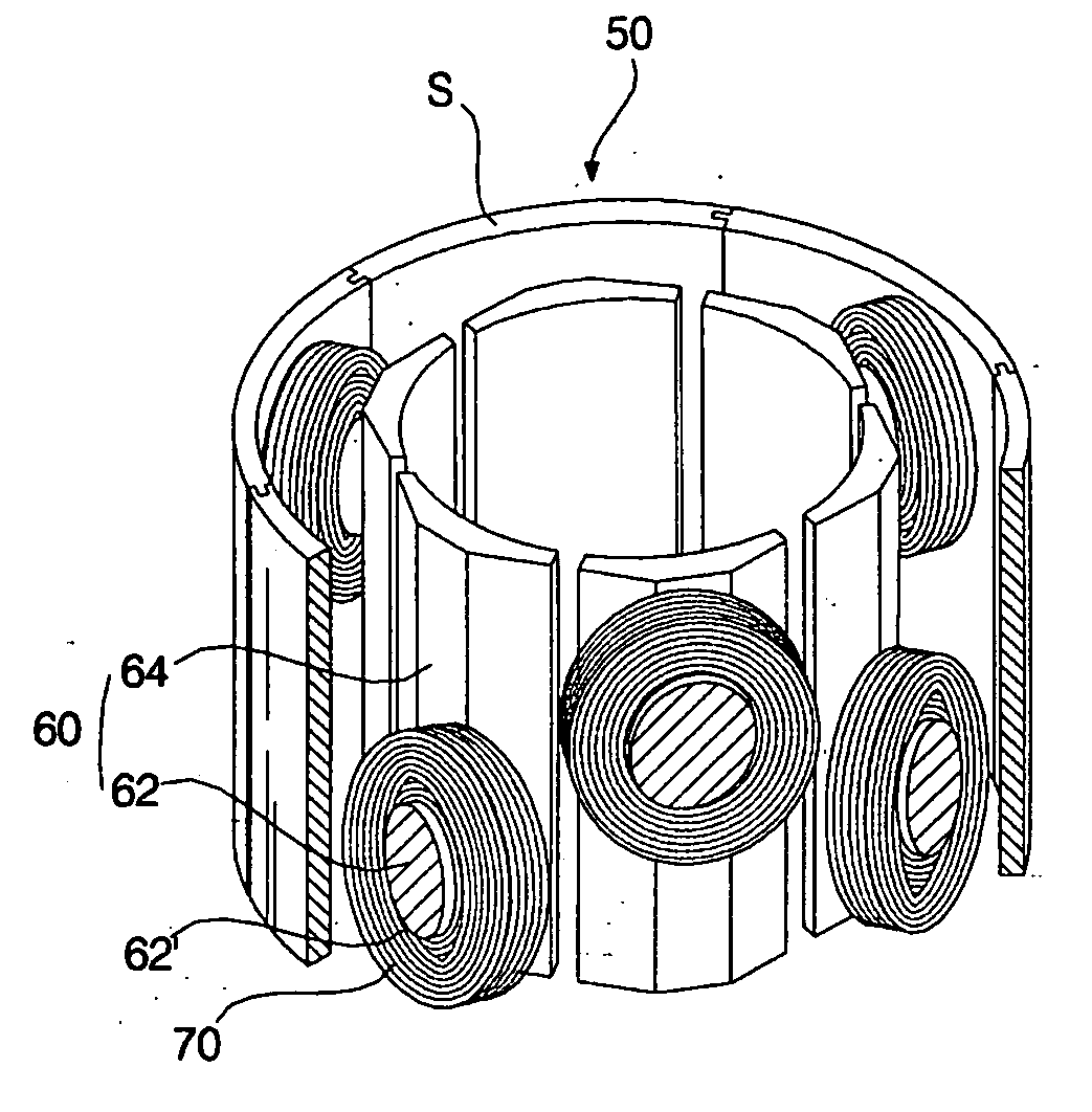
[0034]FIG. 7 is a perspective view illustrating a stator of a motor according to an embodiment of the present invention. FIG. 8 is a cross-sectional view taken along the line C-C in FIG. 7. FIG. 9 is a partially cutaway perspective view illustrating the stator of the motor according to an embodiment of the present invention. FIG. 10 is an unassembled view, of the teeth of the stator of the motor according to an embodiment of the present invention. FIG. 11 is illustrates the process of assembling the stator of the motor according to an embodiment of the present invention.

[0035] The motor will be described with reference to FIGS. 7 to 11, and is an inner rotor motor in which a rotor is rotatably installed in a stator. The motor shown in FIGS. 7 to 11 includes a ring-shaped yoke 50, teeth 60 arranged on the inner wall of the yoke ...


PUM


Abstract

A stator of a motor includes a yoke; a plurality of teeth located along a circumference of the yoke, each of the teeth including a neck, the necks being staggered with respect to a line extending along a circumferential direction of the yoke; and coils wound around the necks.

Description

[0001] This Nonprovisional Application claims priority under 35 U.S.C. §119(a) on Patent Application No. 10-2005-0019138 filed in Korea on Mar. 8, 2005, the entire contents of which are hereby incorporated by reference. BACKGROUND OF THE INVENTION [0002] 1. Field of the Invention [0003] The present invention relates to a motor, and more particularly, to a stator of a motor in which the necks of the teeth in the circumferential direction of the stator are alternately arranged in the axial direction. [0004] 2. Description of the Related Art [0005]FIG. 1 is a perspective view illustrating a stator of a conventional motor. FIG. 2 is a partially cutaway perspective view illustrating a stator of a conventional motor. FIG. 3 is a cross-sectional view taken along the line A-A in FIG. 1. FIG. 4 is a cross-sectional view taken along the line B-B in FIG. 2. [0006] The conventional motor shown in FIG. 1 to 4 is an inner rotor motor in which a rotor 10 is rotatably installed in a stator 20 and r...

Claims


Application Information

Patent Timeline
Patent Type & Authority Applications(United States)
IPC IPC(8): H02K1/28H02K1/18
CPCH02K1/146A41C3/0007A41C3/128A41C3/144
Inventor SHIM, JANG HOPARK, JIN SOOLEE, SUNG HOKIM, BYUNG TAEK
Owner LG ELECTRONICS INC
Why Eureka
Try Eureka