
Image recording apparatus

a recording apparatus and image technology, applied in the field of image recording apparatus, can solve the problems of paper jam, reverse-side mark or soiling of images on other media, insufficient in terms of preventing cockling, etc., to achieve the effect of improving drying efficiency of recording medium, and preventing cockling of an unacceptable level

Inactive Publication Date: 2006-09-14
FUJIFILM CORP
View PDF1 Cites 10 Cited by
  • Summary
  • Abstract
  • Description
  • Claims
  • Application Information

AI Technical Summary

Benefits of technology

[0010] The present invention is contrived in view of the foregoing circumstances, an object thereof being to provide an image recording apparatus that prevents the occurrence of cockling by efficiently removing solvent remaining on a media.

Problems solved by technology

If cockling of this kind occurs, then the media may make contact with a print head, thereby giving rise to a paper jam.
If this residual ink makes contact with another media, then it may cause reverse-side marks or soiling of the images on other media.
However, in the ink absorbing body, the image forming apparatus, and the image forming method disclosed in Japanese Patent Application Publication No. 2001-179959, though unnecessary solvent is gathered by a solvent absorbing member; there is no specific disclosure regarding the time until removal of the solution, and the relationship between solution removal and the type of medium.
Thus, the disclosure of Japanese Patent Application Publication No. 2001-179959 is not sufficient in terms of preventing cockling.
Moreover, there is no specific disclosure regarding the time until removal of solution, and the relationship between the type of the medium and the solution removal.

Method used


Image

  • Image recording apparatus
  • Image recording apparatus
  • Image recording apparatus

Examples


embodiment 1

Block Division: Specific Embodiment 1

[0205] Next, a specific example of the division of blocks is described below.

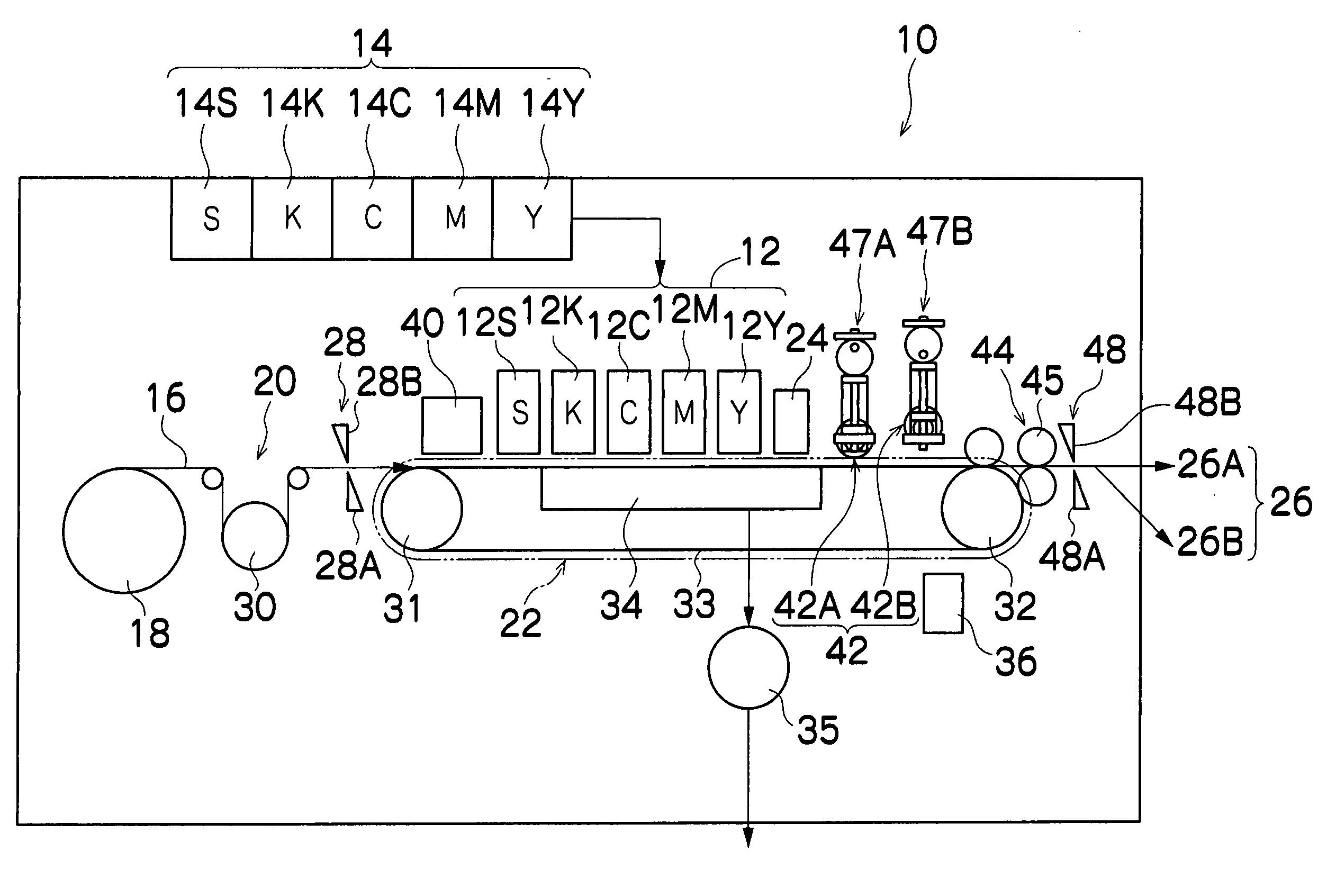
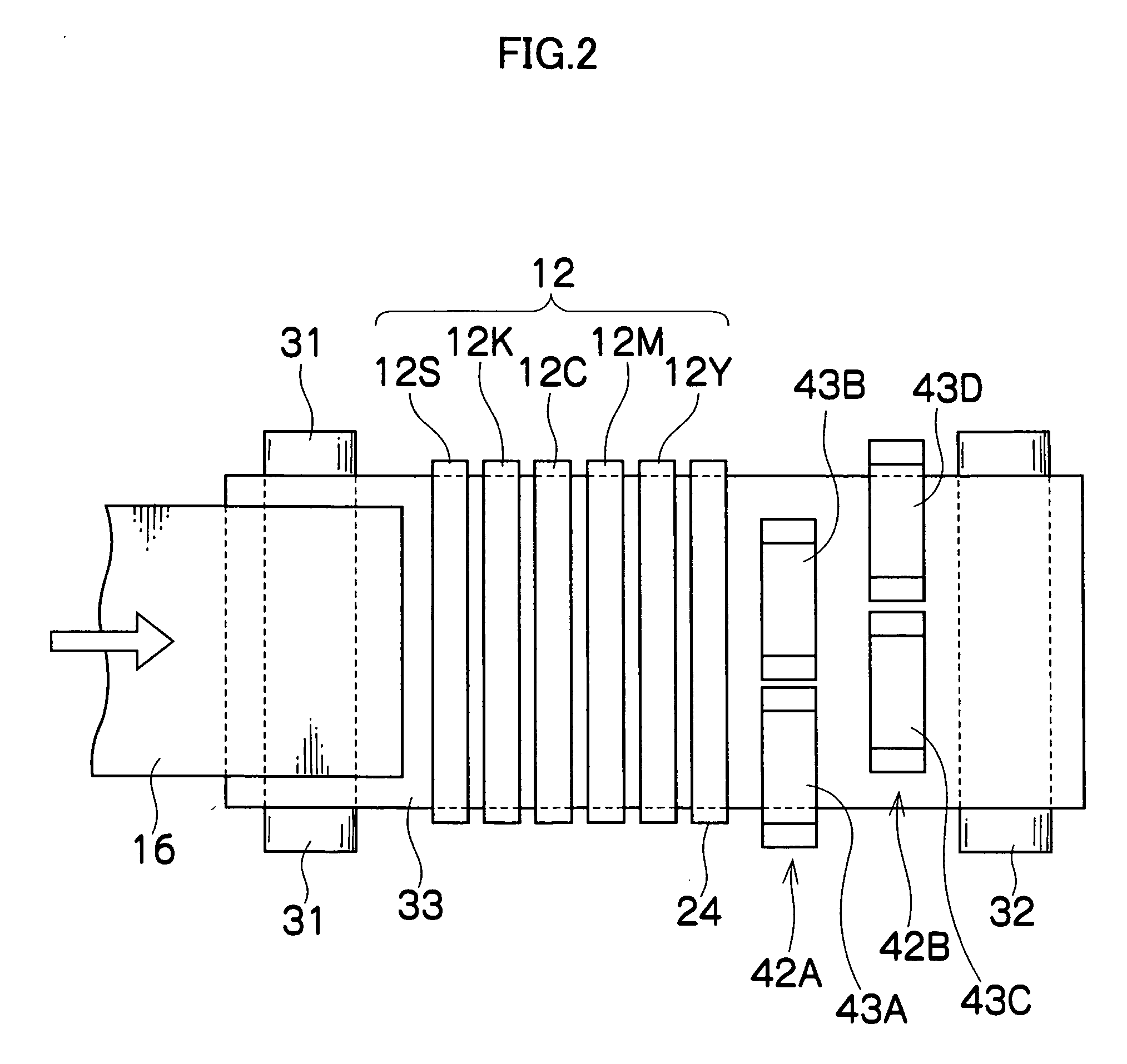
[0206]FIG. 17 shows an example where the width in the main scanning direction of each block established on the recording paper 16 is determined according to the width of the absorbing rollers 43. FIGS. 18 to 21 show an example where regions corresponding to a high solvent volume are extracted on the basis of the image data, and the blocks are established on the recording paper 16 on the basis of these extracted regions.

[0207] As shown in FIG. 17, the width HB in the main scanning direction of each block (R (1, 1) to R (4, 4), . . . ) is set to be slightly smaller than the width HR in the main scanning direction of the absorbing rollers 43. The length L of each block in the paper feed direction is determined from the viewpoint of cockling effects. It is desirable that the size of each block shown in FIG. 17 be changed in accordance with the type of recording paper 16, s...

embodiment 2

Block Division: Specific Embodiment 2

[0211] Next, a further example of dividing the blocks is described below with reference to FIGS. 18 to 21. In this block division method, firstly, regions having continuously high solvent volume, such as pictures, are extracted, whereupon the size of the blocks is determined so as to correspond to these regions.

[0212]FIG. 18 shows an image 418 including pictures 410 and 412, and text areas 414 and 416. The term “image” here does not simply refer to an image in the sense of a photograph or picture, but also includes images in a wider sense, such as text images containing text characters, symbols, pictorial characters and the like, and line images.

[0213] The pictures 410 and 412 are extracted from the image 418 shown in FIG. 18, and square-shaped blocks R (x, y) (reference numerals 440 and 460) having edges of length L′ are set for these pictures 410 and 412. The length of each edge of the blocks R (x, y) shown in FIG. 18 is determined in view of...


PUM


Abstract

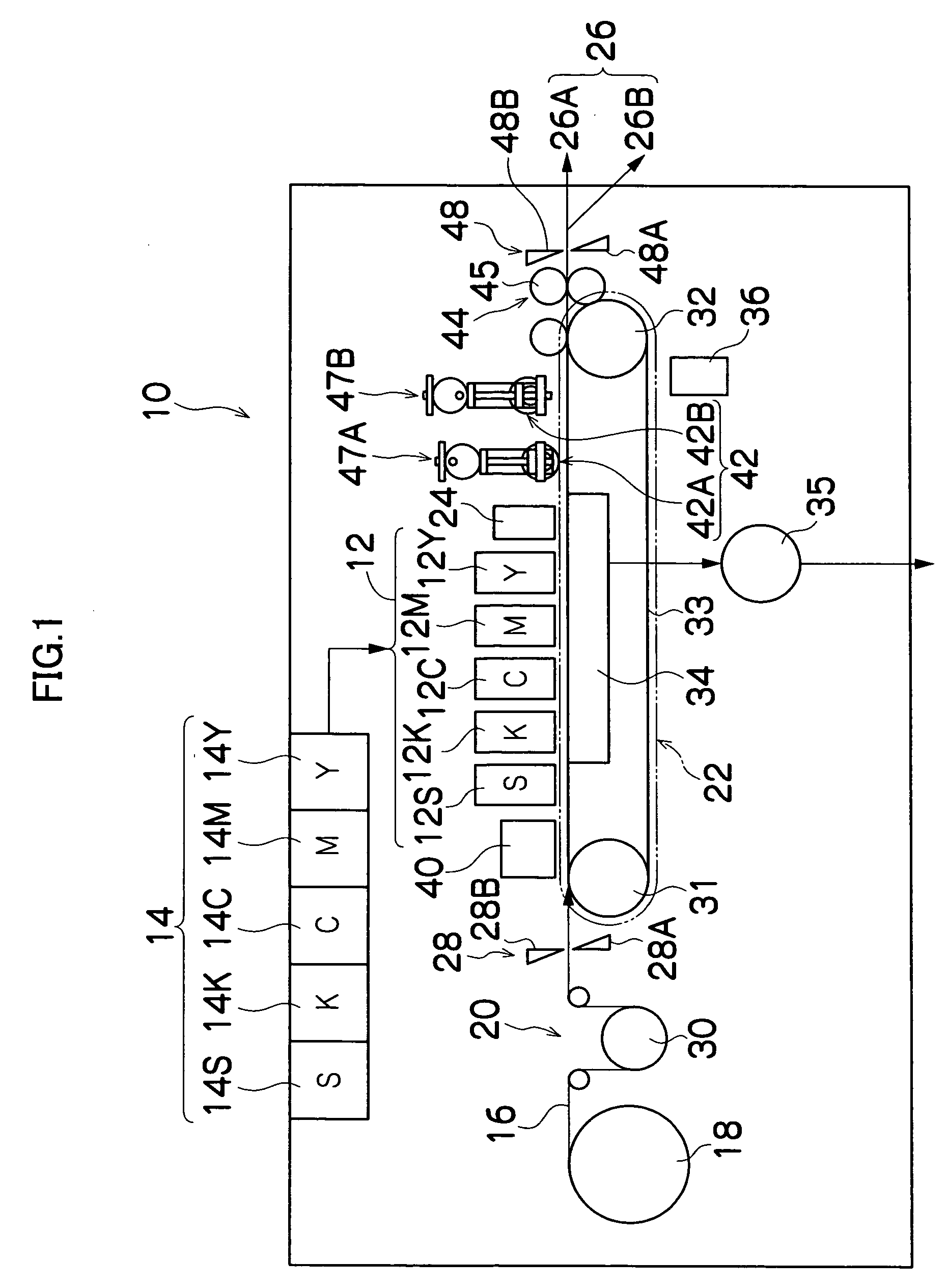
The image recording apparatus comprises: a liquid ejection head which ejects liquid onto a recording medium; a conveyance device which relatively conveys the recording medium with respect to the liquid ejection head, by moving at least one of the recording medium and the liquid ejection head; a liquid removal device which is provided after the liquid ejection head in terms of a conveyance direction of the recording medium and removes the liquid on the recording medium; a recording medium determination device which determines a type of the recording medium; a liquid volume determination device which determines a volume of the liquid on the recording medium; a liquid volume threshold value establishment device which establishes a liquid volume threshold value in accordance with the type of the recording medium determined by the recording medium determination device; and a liquid removal control device which controls the liquid removal device in accordance with a comparison between the volume of the liquid on the recording medium determined by the liquid volume determination device and the liquid volume threshold value established by the liquid volume threshold value establishment device.

Description

BACKGROUND OF THE INVENTION [0001] 1. Field of the Invention [0002] The present invention relates to an image recording apparatus, and more particularly, to liquid removal technology that prevents the occurrence of cockling by effectively removing surplus liquid on a recording medium. [0003] 2. Description of the Related Art [0004] In recent years, inkjet recording apparatuses have come to be used widely as data output apparatuses for outputting images, documents, or the like. An inkjet recording apparatus ejects ink from nozzles by driving actuators corresponding to nozzles provided in a print head in accordance with data, and thereby forms an image, document, or the like, corresponding to the data, on a recording medium. [0005] Inkjet recording apparatuses often use water-based inks in which coloring material and additives are mixed with a solvent of water, from the viewpoint of easy handling. Water-based ink permeates into the media, and if the amount of permeated ink exceeds a p...

Claims


Application Information

Patent Timeline
IPC IPC(8): B41J29/38
CPCB41J2/175B41J29/393B41J2002/14459B41J2202/20B41J2/2114B41M7/00
Inventor INOUE, HIROSHI
Owner FUJIFILM CORP
Learn More