

Compensated lcd of the ips mode
Inactive Publication Date: 2006-09-14
MERCK PATENT GMBH
View PDF8 Cites 17 Cited by
- Summary
- Abstract
- Description
- Claims
- Application Information
AI Technical Summary
Problems solved by technology
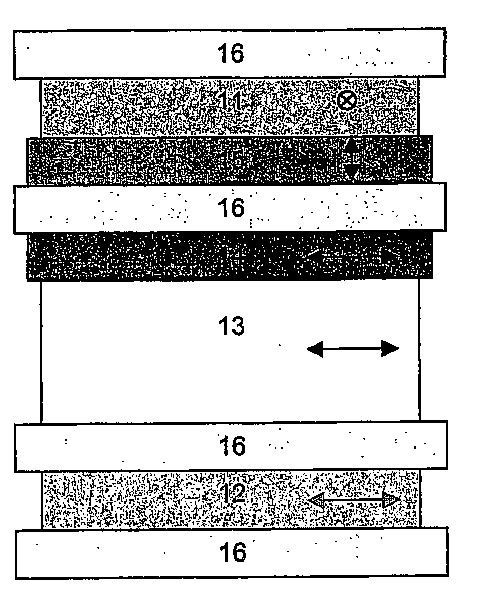
The viewing angle of IPS mode LCD is usually good, however at certain oblique viewing angles, the image quality can deteriorate.
However, the compensation sheets described in prior art to compensate IPS mode displays are either difficult to manufacture on a large scale, like e.g. the homeotropically aligned discotic film as described in U.S. Pat. No. 6,184,957, or tend to suffer from some durability problems described and are particularly difficult to manufacture for large area displays, like e.g. the stretched polymeric films which are usually employed as +A and +C plates.
In addition the manufacturing costs of an IPS compensator are often relatively expensive because the A-plate should preferably be located such its slow axis is perpendicular to the stretch direction of the polariser.
In the case of NB-IPS displays these films often deteriorate the viewing angle of the display and are, in effect additional features which must be compensated.
Method used
View moreImage
Smart ImageViewing Examples

Examples
example 1
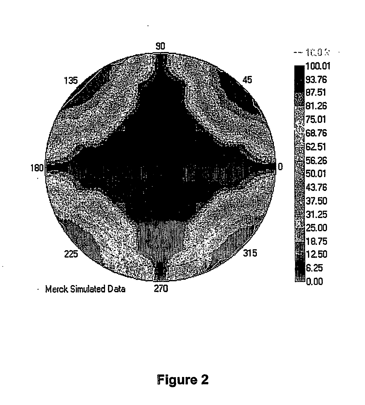
[0132] An IPS display comprises a compensator with a +A plate and a +C plate according to configuration No. 1 of table 1 above. The simulated isocontrast plot is shown in FIG. 3.
example 2
[0133] An IPS display comprises a compensator with a +A plate and a +C plate according to configuration No. 4 of table 1 above. The simulated isocontrast plot is shown in FIG. 4.
example 3
[0134] An IPS display comprises a compensator with a +A plate and a +C plate according to configuration No. 1 of table 2 above, including TAC films as polariser substrates. The simulated isocontrast plot is shown in FIG. 5.
Login to View More PUM
 Abstract
The invention relates to a compensated liquid crystal display (LCD) of the In Plane Switching (IPS) mode and to a compensator for use in an IPS-LCD.
Description
FIELD OF THE INVENTION [0001] The invention relates to a compensated liquid crystal display (LCD) of the In Plane Switching (IPS) mode and to a compensator for use in an IPS-LCD. BACKGROUND AND PRIOR ART [0002] Liquid Crystal Displays (LCDs) are widely used to display information. LCDs are used for direct view displays, as well as for projection type displays. Electro-optical modes employed are e.g. the twisted nematic (TN)-, the super twisted nematic (STN)-, the optically compensated bend (OCB)- and the electrically controlled birefringence (ECB)-mode with their various modifications, as well as others. All these modes use an electrical field, which is substantially perpendicular to the substrates, respectively to the liquid crystal layer. Besides these modes there are also electro-optical modes employing an electrical field substantially parallel to the substrates, respectively the liquid crystal layer, like e.g. the In-Plane Switching mode as disclosed e.g. in DE 40 00 451 and EP...
Claims
Login to View More Application Information
Patent Timeline
 IPC IPC(8): G02F1/1335G02F1/13363G02F1/1343
CPCG02F1/13363G02F1/133634G02F1/134363G02F1/1335
InventorPARRI, OWAIN LLYRRSKJONNEMAND, KARLVERRALL, MARK
OwnerMERCK PATENT GMBH