Image scanning lens and image reader that uses same

Inactive Publication Date: 2006-09-14
FUJI PHOTO OPTICAL CO LTD
View PDF3 Cites 14 Cited by
  • Summary
  • Abstract
  • Description
  • Claims
  • Application Information

AI Technical Summary

Benefits of technology

[0005] The present invention relates to an image scanning lens that has a wide field angle while being compact and that displays good optical performance. The present invention further relates to an image reader provided with such an image scanning lens. In addition, the present invention relates to an image scanning lens that favorably corrects aberrations, especially chromatic aberration, from the visible region to the near-infrared region and an image reader provided with such an image scanning lens.

Problems solved by technology

On the other hand, unnecessary image information such as very fine scratches and dust on a film surface are read along with the image as part of the original target information when high resolution imaging is used.
However, the imaging optical systems disclosed in the Japanese applications mentioned above have a relatively small field angle.
Although this is acceptable for reading smaller film such as thirty-five millimeter film, there is a need to upgrade the lens in order to read larger film and reflecting originals (for example, about A4 size), which cannot be done with these imaging systems.

Method used


Image

  • Image scanning lens and image reader that uses same
  • Image scanning lens and image reader that uses same
  • Image scanning lens and image reader that uses same

Examples


embodiment 1

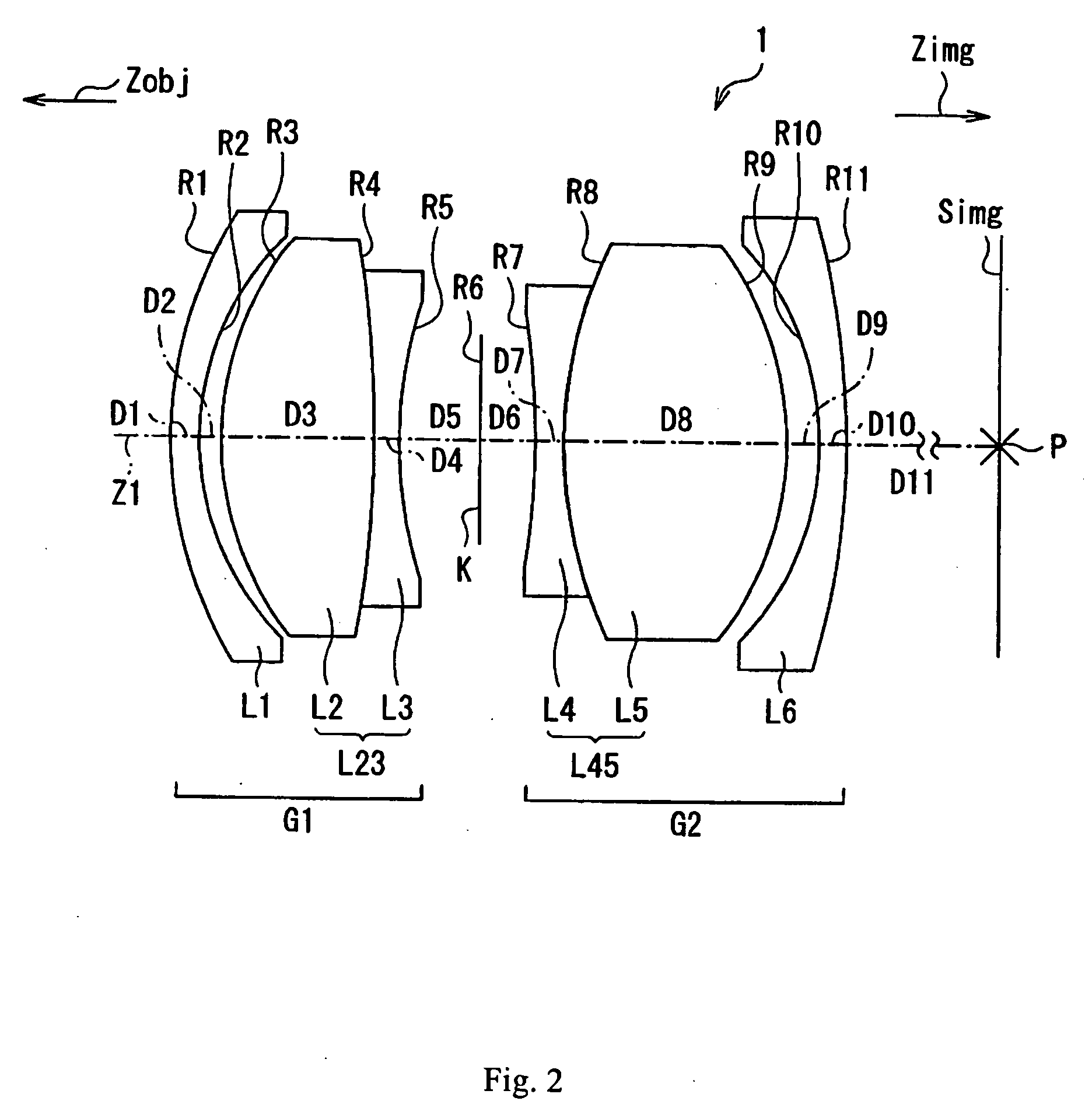
[0049]FIG. 2 shows a cross-sectional view of Embodiment 1 of the image scanning lens of the present invention.

[0050] Table 1 below lists the surface number # in order from the object side, the radius of curvature R (in mm) of each surface, the on-axis surface spacing D (in mm), the refractive index Nd (at the d-line), the refractive index Ng (at the g-line), the refractive index NF (at the F-line), the refractive index NC (at the C-line), the refractive index N(850) (at 850 nm), and the product name that the manufacturer (OHARA) uses to identify the optical material used to make each lens element for Embodiment 1. Listed in the middle portion of Table 1 are the surface number # in order from the object side, the Abbe number νd (at the d-line), the partial dispersion ratio θg,d, the right side of Condition (6) above, and the right side of Condition (7) above for the optical material (other than air) on the image side of the given surface for Embodiment 1. Furthermore, listed in the ...

embodiment 2

[0053] Embodiment 2 of the image scanning lens of the present invention is very similar to Embodiment 1 and is well shown by FIG. 2 that shows a cross-sectional view of Embodiment 1 of the image scanning lens of the present invention.

[0054] Table 2 below lists the surface number # in order from the object side, the radius of curvature R (in mm) of each surface, the on-axis surface spacing D (in mm), the refractive index Nd (at the d-line), the refractive index Ng (at the g-line), the refractive index NF (at the F-line), the refractive index NC (at the C-line), the refractive index N(850) (at 850 nm), and the product name that the manufacturer (OHARA) uses to identify the optical material used to make each lens element for Embodiment 2. Listed in the middle portion of Table 2 are the surface number # in order from the object side, the Abbe number νd (at the d-line), the partial dispersion ratio θg,d, the right side of Condition (6) above, and the right side of Condition (7) above fo...

embodiment 3

[0057] Embodiment 3 of the image scanning lens of the present invention is very similar to Embodiment 1 and is well shown by FIG. 2 that shows a cross-sectional view of Embodiment 1 of the image scanning lens of the present invention.

[0058] Table 3 below lists the surface number # in order from the object side, the radius of curvature R (in mm) of each surface, the on-axis surface spacing D (in mm), the refractive index Nd (at the d-line), the refractive index Ng (at the g-line), the refractive index NF (at the F-line), the refractive index NC (at the C-line), the refractive index N(850) (at 850 nm), and the product name that the manufacturer (OHARA, except where labeled otherwise) uses to identify the optical material used to make each lens element for Embodiment 3. Listed in the middle portion of Table 3 are the surface number # in order from the object side, the Abbe number νd (at the d-line), the partial dispersion ratio θg,d, the right side of Condition (6) above, and the righ...


PUM


Abstract

An image scanning lens includes, arranged in order from the object side, a first lens element having negative refractive power and a meniscus shape with its convex surface on the object side, a biconvex second lens element and a biconcave third lens element that are cemented together, a stop, a biconcave fourth lens element and a biconvex fifth lens element that are cemented together, and a sixth lens element having negative refractive power and a meniscus shape with its convex surface on the image side. The image scanning lens may include only these six lens elements. The image scanning lens satisfies certain conditions related to the focal lengths of the first lens element, the second and third lens elements together, the entire image scanning lens, radii of curvature of various surfaces, and anomalous dispersion of various lens elements. An image reader with an image pickup device, such as a CCD, uses the image scanning lens.

Description

FIELD OF THE INVENTION [0001] The present invention relates to an image scanning lens and to an image reader, such as an image scanner or similar device, that uses such an image scanning lens. BACKGROUND OF THE INVENTION [0002] Image readers are known in which an image of an original color document is formed on a solid state image pickup element such as a CCD (Charge Coupled Device) via an optical system in order to read image information from the original color document. Recently, such image readers also enable reading film originals because of the remarkable progress made in providing high resolution in image readers, such as image scanners. [0003] On the other hand, unnecessary image information such as very fine scratches and dust on a film surface are read along with the image as part of the original target information when high resolution imaging is used. Therefore, attempts have been made to detect the unnecessary image information, such as scratches and dust, by irradiating ...

Claims


Application Information

Patent Timeline
IPC IPC(8): G02B9/00
CPCG02B9/58G02B13/146G02B13/16G02B13/24
Inventor YAMAMOTO, YOKO
Owner FUJI PHOTO OPTICAL CO LTD
Why Eureka
Try Eureka