
DC/AC inverter

a technology of inverter and inverter, which is applied in the direction of electric variable regulation, process and machine control, instruments, etc., can solve the problems of complex circuit design and difficult circuit design, and achieve the effect of lowering noise and lowering dc voltage rippl

Inactive Publication Date: 2006-09-14
BEYOND INNOVATION TECH
View PDF1 Cites 11 Cited by
  • Summary
  • Abstract
  • Description
  • Claims
  • Application Information

AI Technical Summary

Benefits of technology

[0015] Another object of the present invention is to provide a DC / AC inverter for driving a backlight fluorescent lamp of a LCD, especially for a plurality of DC / AC inverters designed for driving a plurality of fluorescent lamps, wherein the DC / AC inverter utilizes less power switches and a set of driving signals to alternatively turn on and off NMOS power switches and PMOS power switches for lowering DC voltage ripple is produced, which in turn lowers noise caused by system ripples caused by switching of power switches.
[0016] Another object of the present invention is to provide a DC / AC inverter for driving a backlight fluorescent lamp of a LCD, which utilizes driving signals to directly drive power switches without step-up circuits. Therefore, the DC / AC inverter has advantages of easy circuit design and lower manufacturing cost.
[0018] Another object of the present invention is to provide two sets of DC / AC inverters such that the DC / AC inverters can provide two sets of driving signals, which are applied to drive half-bridge power switch circuit and have the symmetric waveform of the duty cycle, such that two sets of the power switches would not be conducted simultaneously for lowering DC voltage ripple.

Problems solved by technology

However, since LCD is operated by its optical rotation and optical characteristic to display image and text information, hence not illuminable, it requires an additional backlight source.
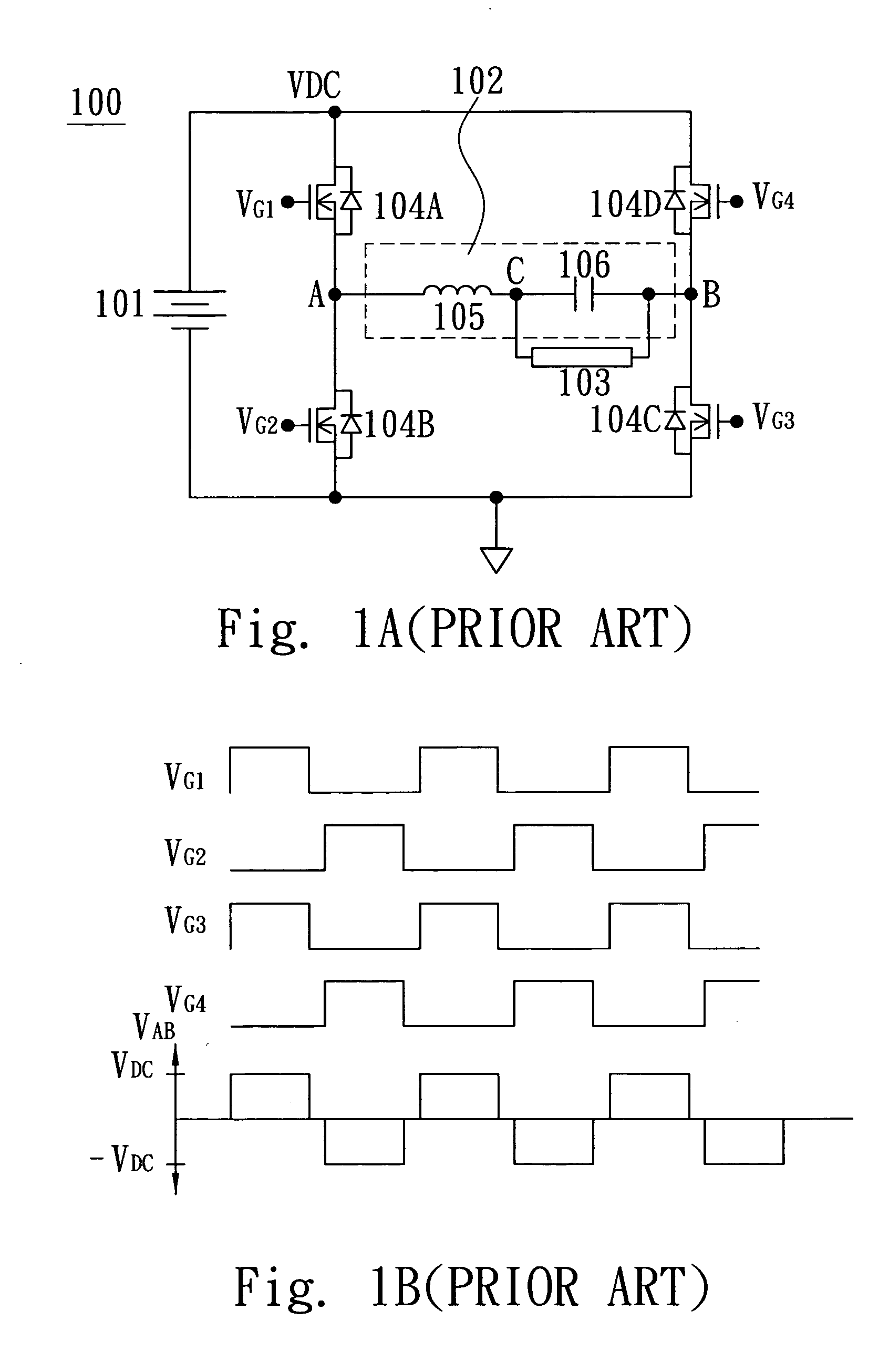
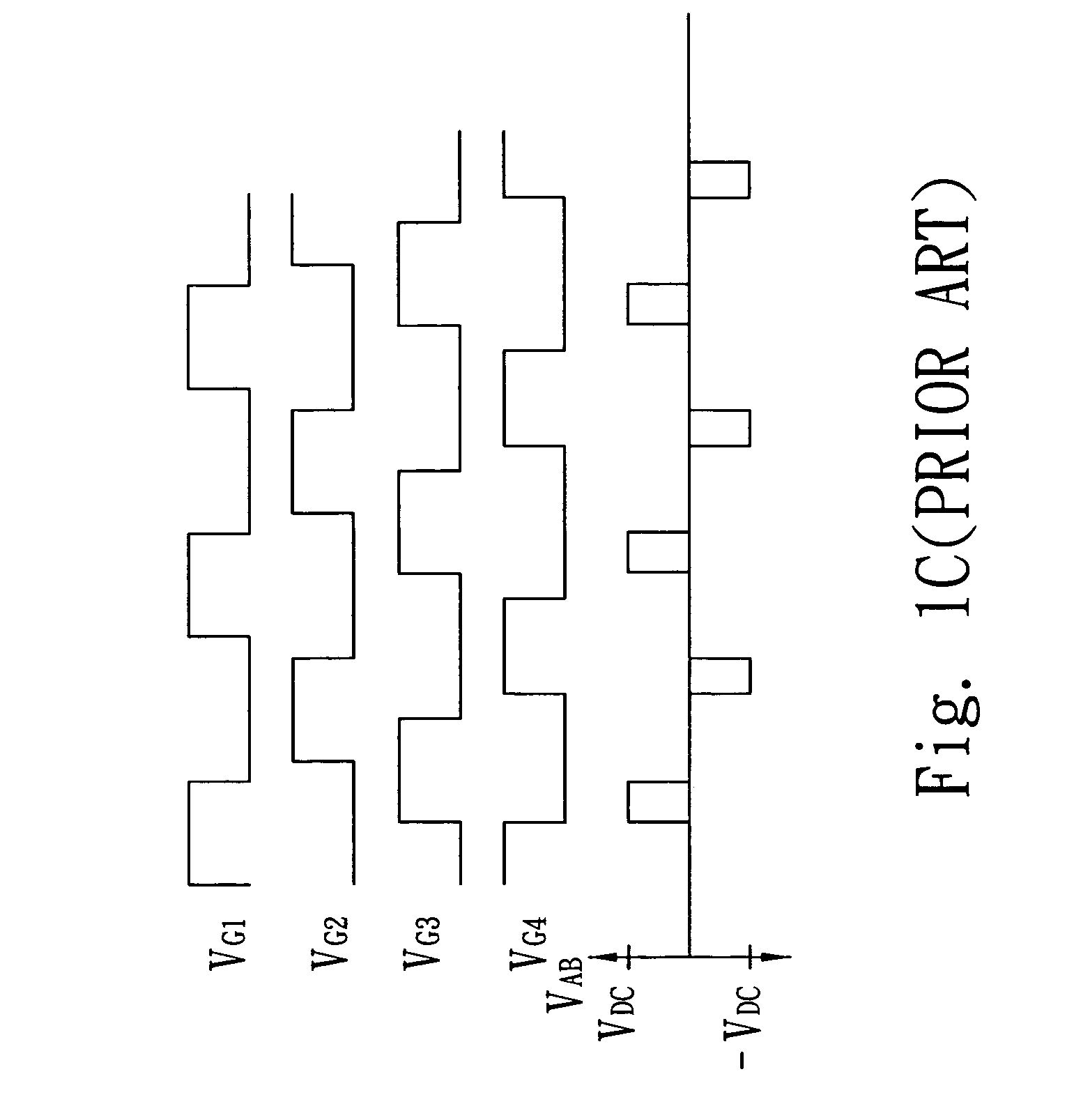
As a result, an additional step-up circuit is required to boost the driving signals VG1 or VG4, however, circuit design is difficult and complicated.

Method used


Image

  • DC/AC inverter
  • DC/AC inverter
  • DC/AC inverter

Examples


Embodiment Construction

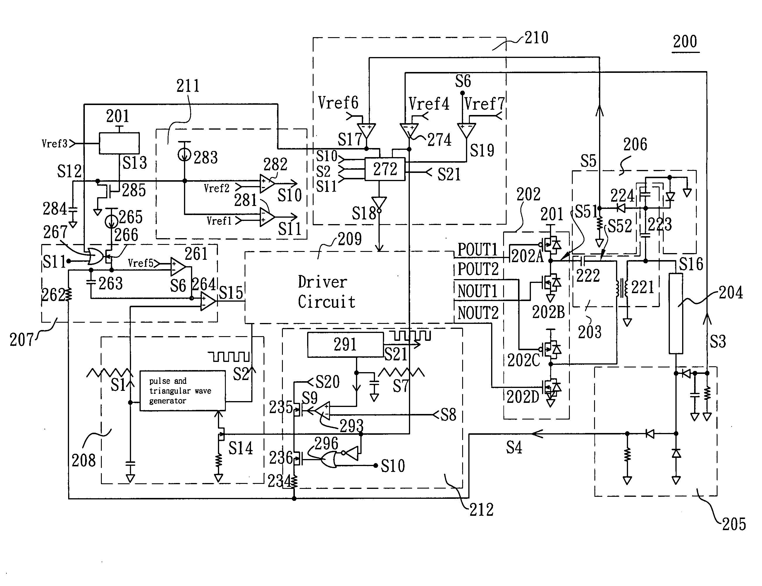
[0033] Referring to FIG. 2 of the drawings, a circuitry of a DC / AC inverter according to the preferred embodiment of the present invention is illustrated. As shown in the drawing, an inverter controller 200 comprises a DC power source 201, a set of MOS power switch 202, a resonant tank 203, a fluorescent lamp 204, a current detecting circuit 205, a voltage detecting circuit 206, a pulse width modulator 207, a frequency generator 208, a driver circuit 209, a protection circuit 210, a timer 211 and a dimming control circuit 212. The DC power source 201 is coupled to the power switch 202. An output of the set of power switch 202 is coupled to an input of the resonant tank 203. An output of the resonant tank 203 is coupled to one end of the fluorescent lamp 204. In this invention, the resonant tank 203 could be any type of the transformer such as Meg-transformer and Piezo-transformer but could not be limited to any type of the transformer. The resonant tank 203 further comprises a step-...


PUM


Abstract

A DC / AC inverter for transforming a DC power source to an AC power, which drives a load. The DC / AC inverter comprises a full-bridge switch circuitry, a resonant tank, a frequency generator and a driver circuit. The full-bridge switch circuitry is electrically connected to the DC power source to convert the DC voltage to a pulse signal. The full-bridge switch circuitry comprises a first power switch, a second power switch, a third power switch, and a fourth power switch. The resonant tank is electrically connected between the full-bridge switch circuitry and a load for boosting and filtering the pulse signal to generate an AC power supplied to the load. The frequency generator generates a pulse signal at one of at least two predetermined operating frequencies based on an operation state of the DC / AC inverter. The driver circuit is coupled to the frequency generator and provides four driving signals based on the pulse signal of the frequency generator for turning on and off the first power switch, the second power switch, the third power switch, and the fourth power switch respectively. The four driving signals have the same frequency, wherein the duty cycle of two of the four driving signals is smaller than 50% and the duty cycle of the other two of the four driving signals is larger than 50%.

Description

CROSS REFLERENCE TO RELATED APPLICATIONS [0001] The present application is a continuation-in-part application of U.S. Ser. No. 10 / 968,857, filed Oct. 18, 2004.BACKGROUND OF THE PRESENT INVENTION [0002] 1. Field of Invention [0003] The present invention relates to a DC / AC inverter for driving a cold cathode fluorescent lamp (CCFL) used as a backlight of a liquid crystal display (LCD), and more particularly to a DC / AC inverter for controlling a plurality of power switches to drive a plurality of fluorescent lamps. [0004] 2. Description of Related Arts [0005] As liquid crystal displays (LCDs) are thinner than conventional cathode ray tube (CRT) monitors, they are being used in more and more homes and public display. However, since LCD is operated by its optical rotation and optical characteristic to display image and text information, hence not illuminable, it requires an additional backlight source. An example of backlight source for LCD is a fluorescent lamp. [0006] A typical DC / AC i...

Claims


Application Information

Patent Timeline
Patent Type & Authority Applications(United States)
IPC IPC(8): H02M3/24
CPCH02M7/53871H05B41/2825H05B41/2828Y02B20/186Y02B70/1441Y02B20/00Y02B70/10
Inventor YU, CHUNG-CHELEE, LI-MINHUANG, SHIH-CHUNGHUNG, CHIEN-PANGLEE, CHIH-SHUN
Owner BEYOND INNOVATION TECH
Learn More