
Pre-emphasis adjustment method

Inactive Publication Date: 2006-09-14
NEC CORP
View PDF4 Cites 9 Cited by
  • Summary
  • Abstract
  • Description
  • Claims
  • Application Information

AI Technical Summary

Benefits of technology

[0009] It is an object of the present invention to eliminate the problem of the conventional art, and to provide a pre-emphasis adjustment method and a pre-emphasis adjustment system which can complete the adjustment of the pre-emphasis intensity in a short time length is even in the case of a transmission line having a high transmission bit rate.
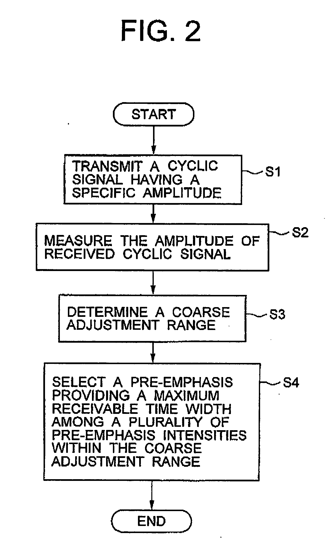
[0012] In accordance with the present invention, the cyclic signal transmitted from the transmitting circuit is measured for the attenuation rate thereof after being transmitted through the transmission line. Based on the attenuated rate of the received cyclic signal, a coarse adjustment range for the pre-emphasis intensity is determined, and a fine adjustment is conducted within the coarse pre-emphasis intensity range, to thereby reduce the time length needed for the pre-emphasis adjustment.
[0013] In a preferred embodiment of the pre-emphasis adjustment method and system of the present invention, the amplitude of the cyclic signal having the specific amplitude is measured in the receiving circuit to determine the roughly adjusted value, or coarsely adjusted value, of the pre-emphasis intensity based on the measured amplitude and the specific amplitude value, and then the pre-emphasis intensity is finely adjusted within the coarse adjustment range, which is determined based on the attenuation of the received cyclic signal, by using the plurality of test signals each having a finely adjusted pre-emphasis intensity within the coarse adjustment range. In this manner, since the adjustment of the pre-emphasis intensity is conducted at two stages including the coarse adjustment stage and the fine adjustment stage, the time length required for adjusting the pre-emphasis intensity can be reduced.

Problems solved by technology

Therefore, if the signal transmission bit rate is high, and if the pre-emphasis intensity that maximizes the receivable time width is to be obtained by trying all of the adjustment values, it takes an extremely large time length to complete the pre-emphasis adjustment.

Method used


Image

  • Pre-emphasis adjustment method
  • Pre-emphasis adjustment method
  • Pre-emphasis adjustment method

Examples


Embodiment Construction

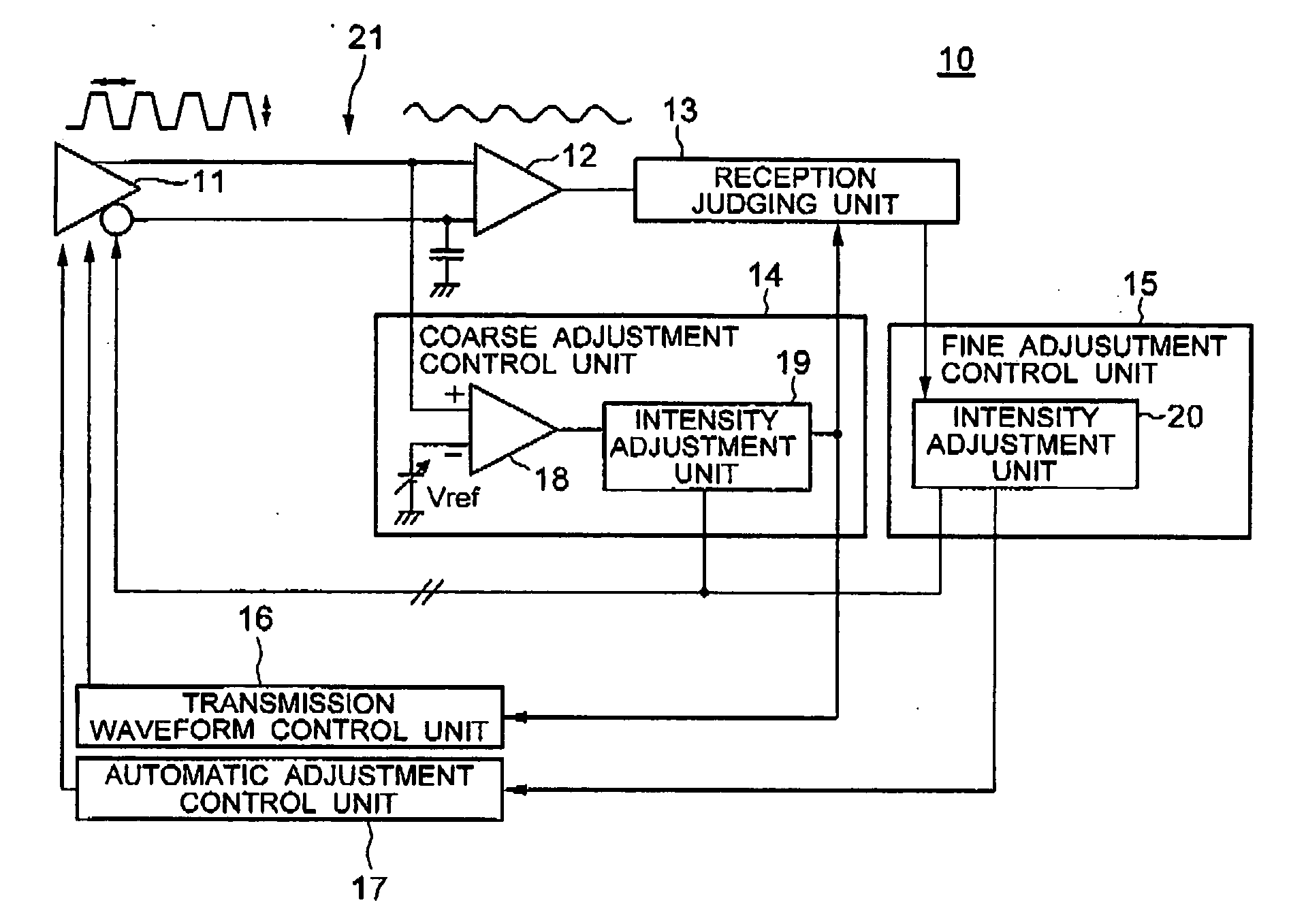
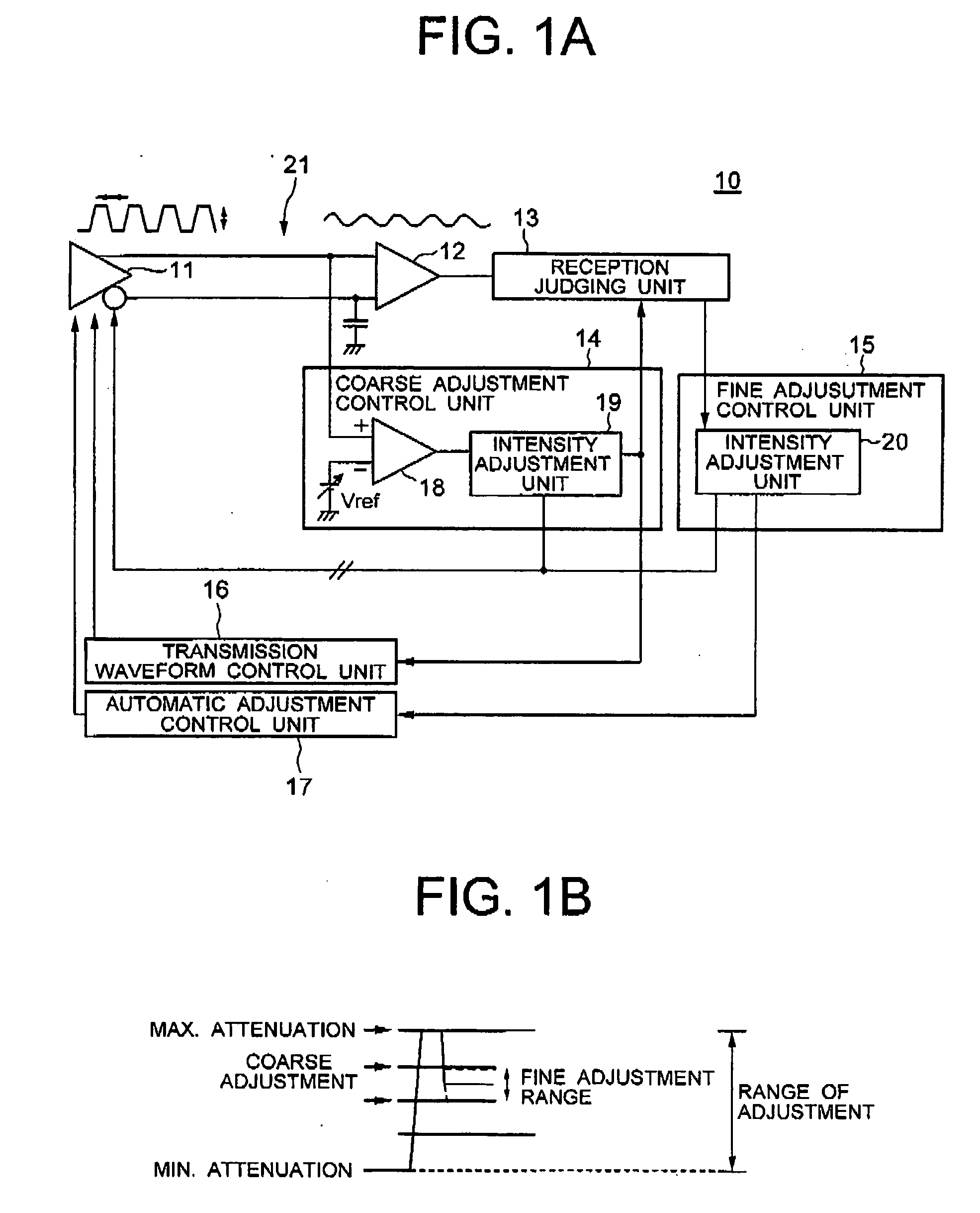
[0017] Preferred embodiments of the present invention will now be described in detail with reference to the accompanying drawings. FIG. 1A shows the configuration of a signal transmission system including a pre-emphasis adjustment system according to an embodiment of the present invention. The signal transmission system 10 includes a transmitting circuit 11, a signal transmission line 21, a receiving circuit 12, and a pre-emphasis adjustment system installed in the signal transmission system 10.

[0018] The pre-emphasis adjustment system includes a reception judging unit 13, a coarse adjustment control unit 14, a fine adjustment control unit 15, a transmission waveform control unit 16, and an automatic adjustment control unit 17. In the exemplified configuration, the transmitting-side LSI includes the transmitting circuit 11, transmission waveform control unit 16 and automatic adjustment control unit 17, whereas the receiving-side LSI included the receiving circuit 12, reception judg...


PUM


Abstract

A pulse train having a specific amplitude is transmitted from a transmitting circuit, and the amplitude at the receiving end is measured by a comparator. A coarse adjustment control unit determines a coarse adjustment value of the pre-emphasis intensity based on the measured amplitude. The pre-emphasis intensity is changed within the course pre-emphasis range, and the maximum receivable time width of a test signal is obtained by a reception judging unit 13 by using a fine adjustment stage.

Description

BACKGROUND OF THE INVENTION [0001] 1. Field of the Invention [0002] The present invention relates to a pre-emphasis adjustment method and more particularly, to a pre-emphasis adjustment method for controlling the pre-emphasis intensity provided at the transmission side of a signal transmission line based on a received signal. The present invention also relates to a pre-emphasis adjusting system having a pre-emphasis intensity adjusting function. [0003] 2. Description of the Related Art [0004] Generally, in a transmission line, transmission signals in a high frequency range involve a larger attenuation rate. Accordingly, when signals of a plurality of frequency components are transmitted from the transmission side at the same level for all of the frequency components in the signal, there occurs a difference in the amplitude of the signal between the higher frequency components and the lower frequency components at the receiving side which receives the signals through the transmission...

Claims


Application Information

Patent Timeline
IPC IPC(8): H04J14/02
CPCH04L25/0288H04W52/24
Inventor TANABE, MOTOI
Owner NEC CORP
Learn More