
Magnetic disk drive and magnetic disk medium

Inactive Publication Date: 2006-10-12
HITACHI GLOBAL STORAGE TECH NETHERLANDS BV
View PDF3 Cites 0 Cited by
  • Summary
  • Abstract
  • Description
  • Claims
  • Application Information

AI Technical Summary

Benefits of technology

[0008] If it is possible to minimize the power consumption required to accelerate until the HDD enters the high-speed rotation state and the power consumption required to maintain the high-speed rotation state, it becomes possible to lengthen the continuous reproduction time of the portable devices driven by battery. The reduction in power consumption, therefore, was one of the conventional challenges. Here, the power consumption at the time of starting can be reduced by increasing the capacity of a buffer memory, and by decreasing the frequency of starting. However, under the existing circumstances, large-capacity memories having a size of tens of megabytes cost much, and accordingly it is difficult to build such memories into portable devices, which is a main problem.
[0011] The present invention is devised to solve the above-mentioned problems. A feature of the present invention is to provide a magnetic disk drive in which the power consumption is reduced with the length of time taken to write data to the HDD being shortened, and also to provide a magnetic disk medium used for the magnetic disk drive.
[0014] According to the present invention, write operation is performed at relatively high rotational speed, whereas read operation is performed at relatively low rotational speed. Performing the write operation at high rotational speed makes it possible to reduce the length of time taken to write data to an HDD. On the other hand, if the read operation is performed at low rotational speed, the acceleration at the time of starting up becomes gentle, and a pulse-drive frequency for example at steady rotation is reduced, which enable the reduction in power consumption. Additionally, because data is reproduced from the buffer memory in parallel with the read operation, data can be newly buffered, by read operation, in a buffer area from which the data has already been reproduced. Accordingly, once the HDD is started up, the amount of data which can be successively read out from the HDD increases. In other words, the number of times the HDD is started up is reduced, which enables the reduction in power consumption. If the read operation at low rotational speed is performed by use of only servo data (the first servo data), which is located on a track and is used at the time of write operation, a period of feedback control using the servo data becomes long. This is not desirable from the viewpoint of the position control of a head. For this reason, servo data (the second servo data) used only at the time of read operation is formed between the first servo data and the adjacent first servo data thereof, making it possible to perform stable read operation. Moreover, the second servo data differs from the first servo data. More specifically, it is not necessary to form a gap area adjacent to the second servo data. Accordingly, it is possible to minimize the decrease in user-available storage capacity of a magnetic disk medium, the decrease resulting from writing of the second servo data. Consequently, it becomes possible to store long-time content in the HDD, and thereby to carry the long-time content stored in the HDD on the road.

Problems solved by technology

The reduction in power consumption, therefore, was one of the conventional challenges.
However, under the existing circumstances, large-capacity memories having a size of tens of megabytes cost much, and accordingly it is difficult to build such memories into portable devices, which is a main problem.
Another problem is that if the capacity of the buffer memory is small, the number of times the HDD is turned ON / OFF increases, which may cause a decrease in reliability and an increase in noises.
In other words, for example, if the content which is viewed at home is brought out, the length of time required to store the content is too long, which is also a problem.

Method used


Image

  • Magnetic disk drive and magnetic disk medium
  • Magnetic disk drive and magnetic disk medium
  • Magnetic disk drive and magnetic disk medium

Examples


Embodiment Construction

[0020] Embodiments according to the present invention (hereinafter referred to as “embodiments”) will be described with reference to the drawings as below.

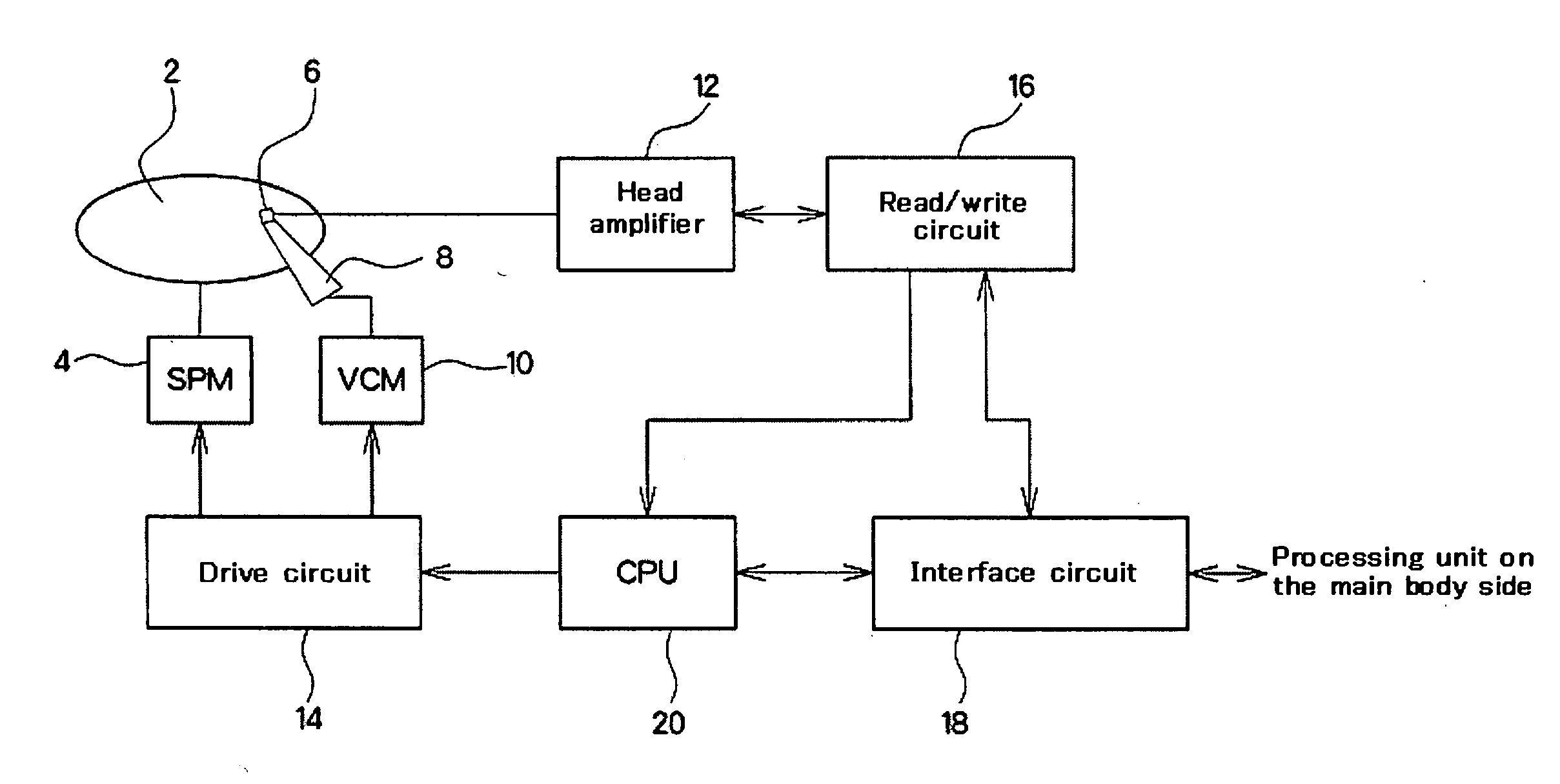
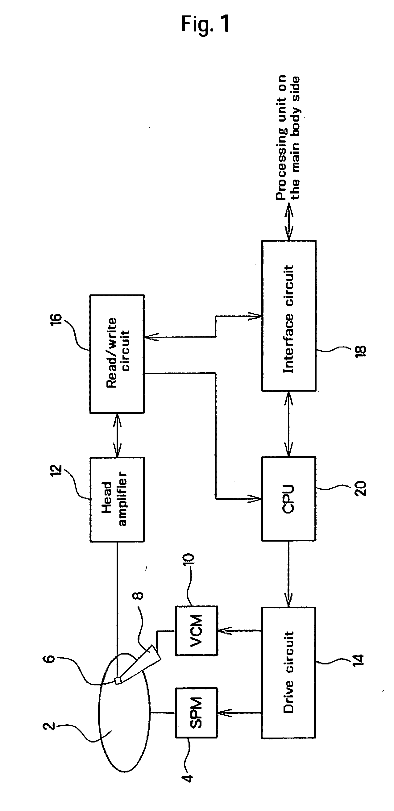
[0021]FIG. 1 is a block diagram schematically illustrating a configuration of a magnetic disk drive according to this embodiment. The magnetic disk drive comprises a magnetic disk medium (disk) 2, a spindle motor (SPM) 4, a head element (head) 6, a head arm 8, a voice coil motor (VCM) 10, a head amplifier 12, a drive circuit 14, a read / write circuit 16, an interface circuit 18, and CPU 20. The magnetic disk drive is built into, for example, personal digital assistants and cellular phones. In addition, the magnetic disk drive is used to store and reproduce music data, video data, and the like.

[0022] Information is magnetically written on the disk 2 along a plurality of tracks that are concentrically formed on surfaces of the disk 2. Each track is partitioned into a plurality of servo sectors by means of servo data written beforeh...


PUM


Abstract

Embodiments of the invention increase the convenience of a magnetic disk drive for portable use by shortening a period of time required to record a large amount of data, and by increasing the reproduction time, in the magnetic disk drive. In one embodiment, an area between servo data parts is interpolated by servo data parts, each of which stores a burst signal, so that the allocation density of a burst signal is made k times. At the time of write operation in which data is written, only the servo data parts are made use of to perform the servo control while a disk is driven at high rotational speed so as to reduce the recording time. At the time of read operation in which data is reproduced, the servo data parts are made use of to ensure the required precision of the servo control at low rotational speed that is 1 / k of the rotational speed at the time of write operation. The reproduction at low rotational speed enables the reduction in power consumption.

Description

CROSS-REFERENCES TO RELATED APPLICATIONS [0001] This application claims priority from Japanese Patent Application No. JP2005-110735, filed Apr. 7, 2005, the entire disclosure of which is incorporated herein by reference. BACKGROUND OF THE INVENTION [0002] The present invention relates to magnetic disk drives and magnetic disk media, and more particularly to magnetic disk drives, and the like, that are suitable for portable devices. [0003] In recent years, with the development of small-size hard disk drives (HDDs), a personal digital assistant, or a cellular phone, has a built-in HDD in which video data and audio data (AV data) are accumulated. The video data and the audio data are reproduced and utilized on the road. The above is the tendency of products that are being developed. As for this portable device, the AV data is stored in the HDD that is a mass storage device; and at the time of reproduction, data is transferred, whenever necessary, from a magnetic disk medium to a buffer...

Claims


Application Information

Patent Timeline
IPC IPC(8): G11B21/02G11B5/09G11B15/46
CPCG11B19/26
Inventor SATOH, NAOKIISHIDA, YOSHITERUWATANABE, YOSHIJUTAKASHI, TERUMI
Owner HITACHI GLOBAL STORAGE TECH NETHERLANDS BV
Learn More