Fiberglass pool edge coping system

a technology of fiberglass pool and coping system, which is applied in the direction of gymnasium, construction, buildings, etc., can solve the problems of non-rigid shell structure generally involves a degree of trial and error, the top edge of the pool liner is out of true relative to typical construction tolerance, and the pool is difficult to install with precision

Inactive Publication Date: 2006-09-21
STANCILL RAYMOND T
View PDF4 Cites 6 Cited by
  • Summary
  • Abstract
  • Description
  • Claims
  • Application Information

AI Technical Summary

Benefits of technology

[0019] This invention greatly improves the edging system of the prior art, providing installers with an easy-to-use system for forming an area to receive a concrete surround, eliminating the need for timely and hurried concrete edge fini...

Problems solved by technology

Finishing the edges of fiberglass in-ground pools with a concrete pad surround has traditionally presented suppliers with challenges.
Because of the size and relative flexibility of the pre-fabricated fiberglass containment liner, an in-ground pool is difficult to install with precision.
Fashioning the bottom and sides of the excavation to fit the bulky, non-rigid shell structure generally involves a degree of trial and error as the installation progresses due to the flex and sag inherent in the liner.
As a result, the top edge of the pool liner tends to be out of level and out of true relative to typical construction tolerances.
This presents difficulties in placing concrete around the perimeter of the pool because using conventional forming methods for concrete work on a hard, non-level edge-surface is impractical.
In addition, many pool designs call for curved rather than straight edges, further complicating the issue of form work for placing concrete.
Thi...

Method used


Image

  • Fiberglass pool edge coping system
  • Fiberglass pool edge coping system
  • Fiberglass pool edge coping system

Examples


first embodiment

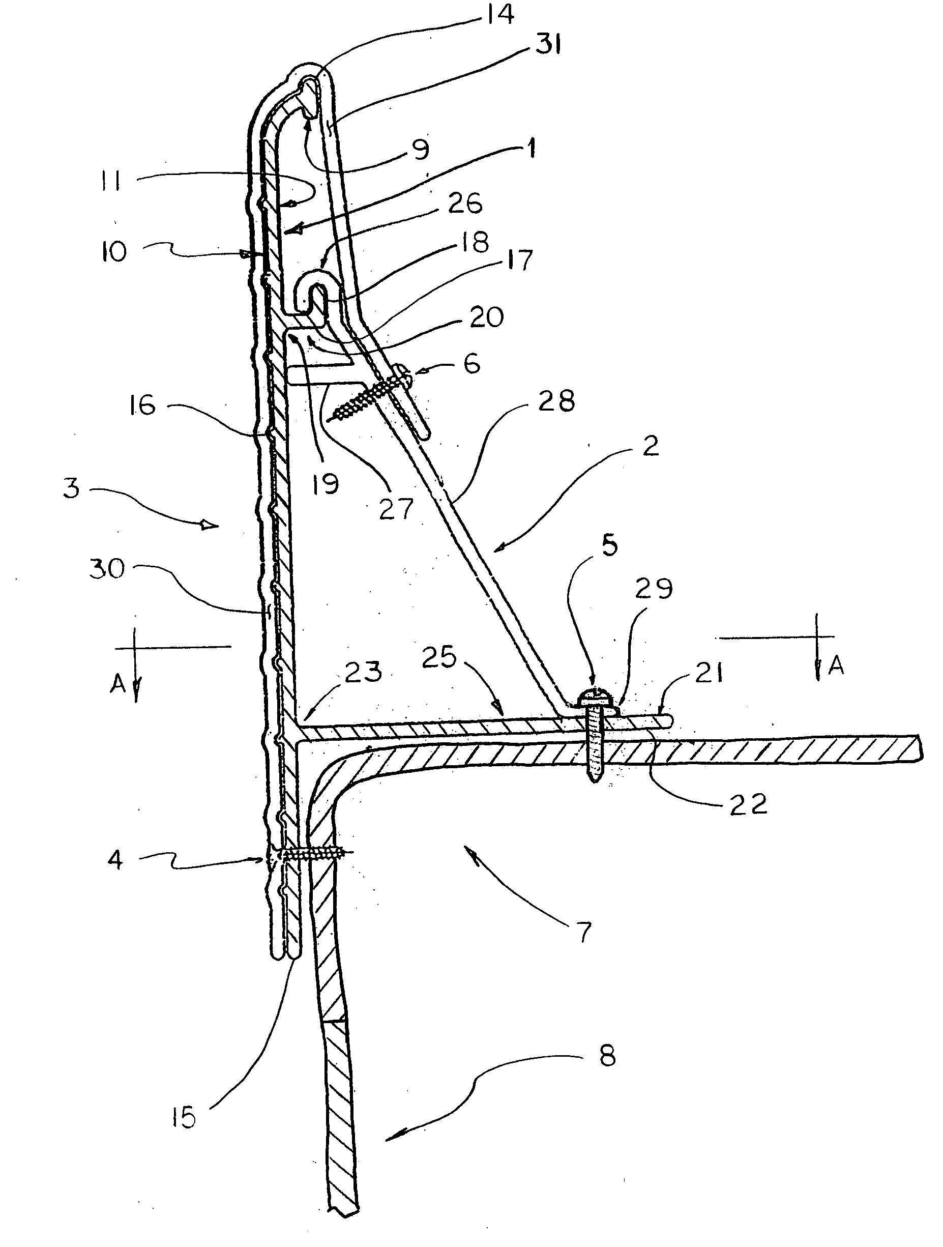
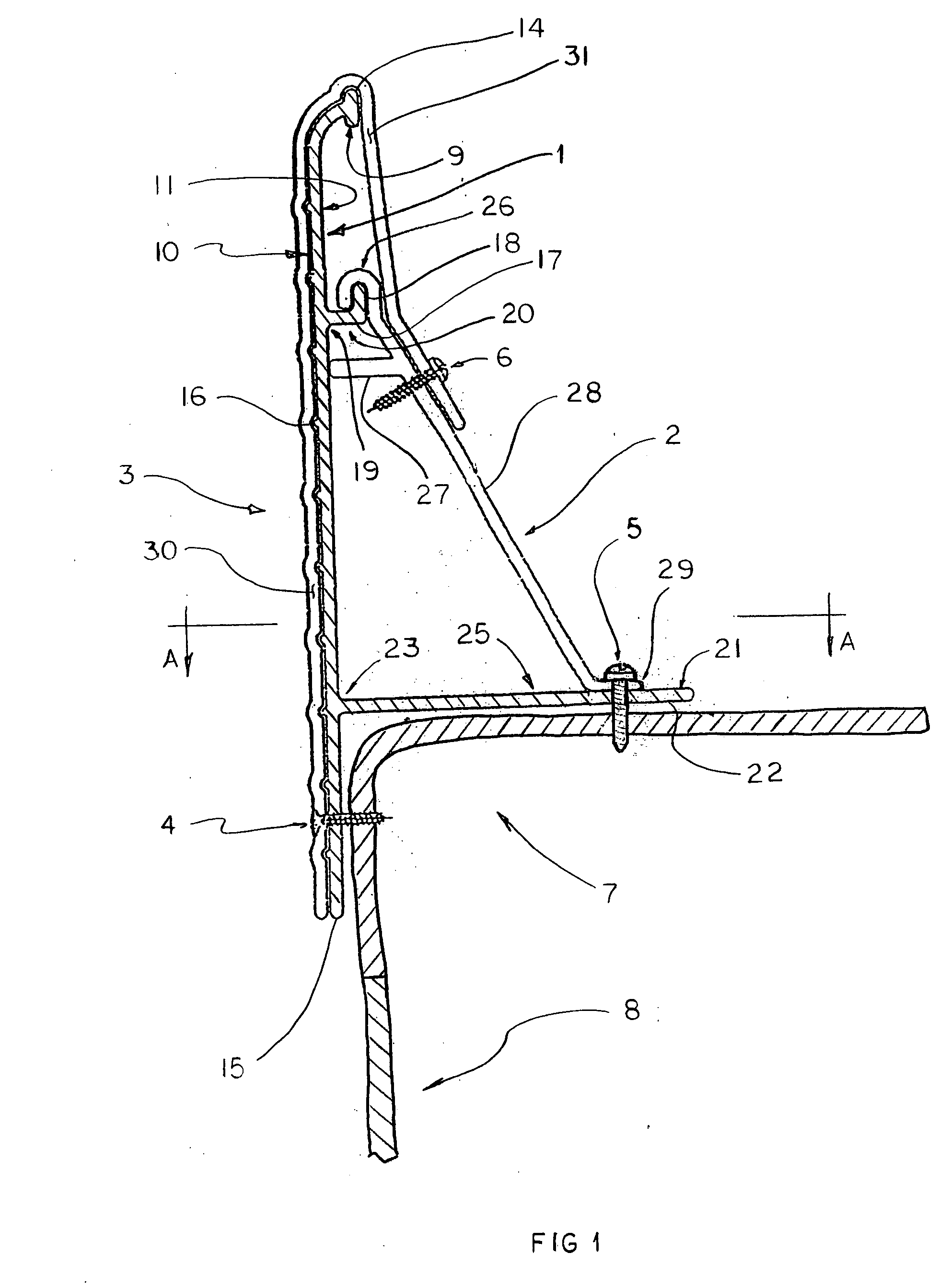
[0042] The installation process of the first embodiment continues, placing additional edging bands, intermediate anchors, joint anchors and joint clips, finishing with a final edging band (not shown) being cut to length and fit to the left end of the first edging band 1L (not shown) in a final butt joint (not shown), until the entire top corner of the pool is edged with the edging band. This creates a continuous edging band (not shown) around the entire perimeter of the pool.

[0043] Once the continuous edging band is ready, additional known preparation of a concrete placement area is completed. Said concrete placement area comprises a prepared surface beginning at said continuous ending band and projecting away from back side 11 of all edging bands comprising said continuous band to a known limit. Concrete is then placed in said concrete placement area, utilizing said continuous edging band as a retaining wall (a concrete form) to prevent a flow of wet concrete into the pool, and sim...

third embodiment

[0046] In a third embodiment, front side 10 may be decorated with paint or a pattern.


PUM


Abstract

A pool edge coping system for completing the water-side edge of a concrete pool surround installed around the top of pre-fabricated, fiberglass in-ground pools. The coping system is a combination concrete placement form and edge finishing system for cast-in-place surrounds. An embodiment of the invention comprises long, thin decorative edging bands secured to the top corner of the pool liner. Multiple band are fastened end-to-end around the perimeter of the pool using fasteners. Anchors are installed at various points along the length of the band to secure its front face in the vertical direction. Joint clips are installed over the ends of the bands at each butt-joint. Concrete is placed against the back of the band, leveled to the top of the band and allowed to cure. The band is left in place as a decorative edging to the completed concrete surround.

Description

FIELD OF THE INVENTION [0001] The present invention relates to the field of in-ground pool finishing systems. More specifically, the present invention is coping system for finishing the edge of an in-ground fiberglass pool. BACKGROUND OF THE INVENTION [0002] Finishing the edges of fiberglass in-ground pools with a concrete pad surround has traditionally presented suppliers with challenges. Because of the size and relative flexibility of the pre-fabricated fiberglass containment liner, an in-ground pool is difficult to install with precision. Fashioning the bottom and sides of the excavation to fit the bulky, non-rigid shell structure generally involves a degree of trial and error as the installation progresses due to the flex and sag inherent in the liner. As a result, the top edge of the pool liner tends to be out of level and out of true relative to typical construction tolerances. This presents difficulties in placing concrete around the perimeter of the pool because using conven...

Claims


Application Information

Patent Timeline
IPC IPC(8): E04H4/00
CPCE04H4/141
Inventor STANCILL, RAYMOND T.
Owner STANCILL RAYMOND T
Why Eureka
Try Eureka