Mount for firearm sighting device having throw-lever clamp and lever safety latch

Inactive Publication Date: 2006-09-21
LARUE MARK C
View PDF7 Cites 80 Cited by
  • Summary
  • Abstract
  • Description
  • Claims
  • Application Information

AI Technical Summary

Benefits of technology

[0009] It is a principal feature of the present invention to provide a throw-lever actuated mount for firearms wherein one or more of the throw-levers of an accessory mount can be secured at it

Problems solved by technology

However, it has also been determined that mechanical clamping devices having throw-levers can become loosened as the firearm is subjected to significant vibration, such as when the firearm is fired rapidly, such as during conditions of sustained rapid fire and has cycled many rounds of ammunition.
Sustained vibration and rough use can cause the throw-levers of accessory mount mechanisms to move, i.e., rotate inadvertently to the release position.
When this condition exists the sighting device of the firearm, whethe

Method used


Image

  • Mount for firearm sighting device having throw-lever clamp and lever safety latch
  • Mount for firearm sighting device having throw-lever clamp and lever safety latch
  • Mount for firearm sighting device having throw-lever clamp and lever safety latch

Examples


Embodiment Construction

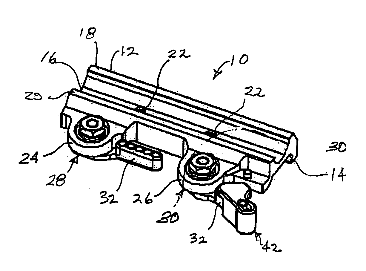
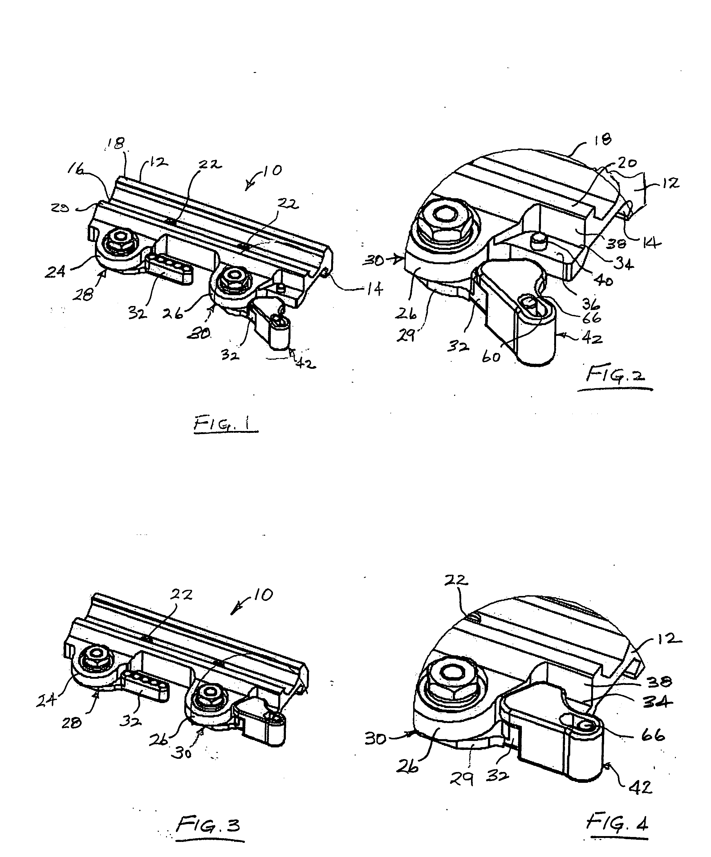
[0027] Referring now to the drawings and first to FIGS. 1 and 2, a clamp type firearm accessory mount mechanism is shown generally at 10 which comprises a clamp or mount base 12 having an elongate clamp member 14 provided thereon. The clamp member 14 maybe integrally formed with the clamp or mount base is desired or it may be fixed to the base member in any suitable fashion and is undercut so as to define an angulated upwardly facing clamping surface for clamping engagement with a correspondingly angulated, but downwardly facing angulated surface of a firearm mounting rail. A mounting rail may be formed integrally with a firearm component, such as a receiver or handguard, or may be fixed to a specified part of a firearm by means of retainer screws or by means of any other suitable fastening device. The mount base 12 has an elongate trough 16 that is defined by parallel flanges 18 and 20. Retainer screws, such as shown at 22 extend through the mounting base if desired to positively f...


PUM


Abstract

For firearms, particularly tactical firearms such as the AR-15 tactical rifle, a throw-lever actuated rail clamp is provided for support of various accessories such as optical sighting devices, laser sighting devices, target lighting devices on various part of a firearm to provide for use of the firearm in variable field conditions, during the day or at night. A mount clamp is releasably secured to a firearm rail by a pivotal throw-lever having an eccentric locking component. A safety latch mechanism is mounted for linear movement on the actuating arm of the throw-lever and is moveable to a latched position engaging a latching element of the clamp base to retain the throw-lever at its clamping position. The safety latch is linearly moveable from its latched position to a release position that permits rotational movement of the throw lever toward its release or non-clamping position.

Description

RELATED PROVISIONAL APPLICATION [0001] Applicant hereby claims the benefit of U.S. Provisional Patent Application No. 60 / 658,865, filed on Mar. 5, 2005 by Mark C. LaRue and entitled “Mount For Firearm Sighting Device Having Throw-lever Clamp and Lever Safety Latch”. RELATED PATENT APPLICATION [0002] The subject matter of the invention set forth herein is related to the subject matter of U.S. patent application Ser. No. 11 / 008,394, filed by Mark C. LaRue on Dec. 9, 2004 and entitled Adjustable Throw-lever Picatinny Rail Clamp, which Application is incorporated herein by reference for all purposes.BACKGROUND OF THE INVENTION [0003] 1. Field of the Invention [0004] The present invention generally relates to mount mechanisms for mounting firearm accessories such as telescopic sighting devices, laser sighting devices, lighting devices and the like to firearms, particularly tactical firearms that are used by military and law enforcement personnel. This invention concerns releasable mounts...

Claims


Application Information

Patent Timeline
IPC IPC(8): F41G1/38
CPCF41G11/003
Inventor LARUE, MARK C.
Owner LARUE MARK C
Why Eureka
Try Eureka