
Electric wheel

Inactive Publication Date: 2006-09-21
TSENG SIN DUN
View PDF7 Cites 8 Cited by
  • Summary
  • Abstract
  • Description
  • Claims
  • Application Information

AI Technical Summary

Benefits of technology

[0007] An objective of the present invention is to provide an electric wheel of which the rotation speed can be easily adjusted by software without need of a high precision speed-changing mechanism so as to effectively mitigate unwanted noise.

Problems solved by technology

Further, using the external transmission mechanism may cause annoying noise and also leads the volume of the entire device to become unsatisfactorily bulky.

Method used


Image

  • Electric wheel
  • Electric wheel
  • Electric wheel

Examples


Embodiment Construction

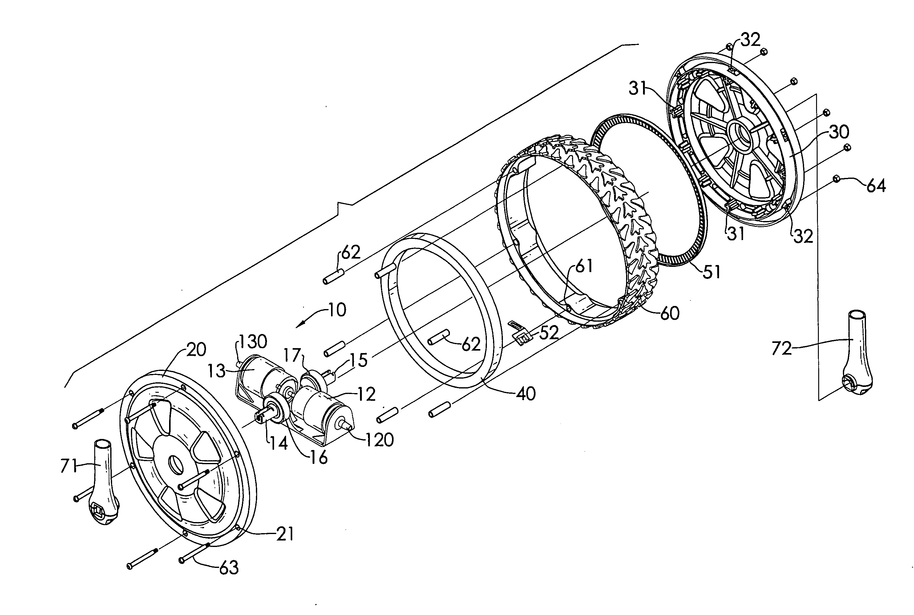
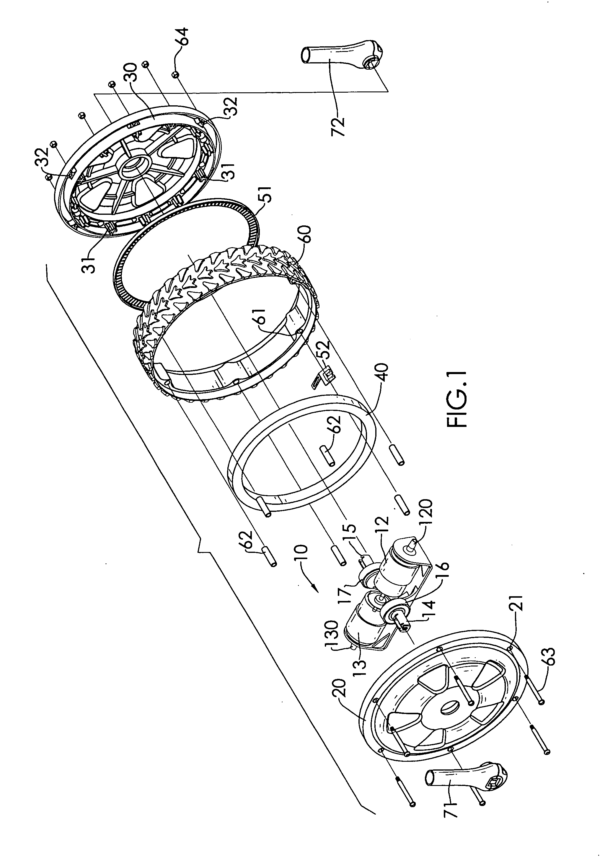
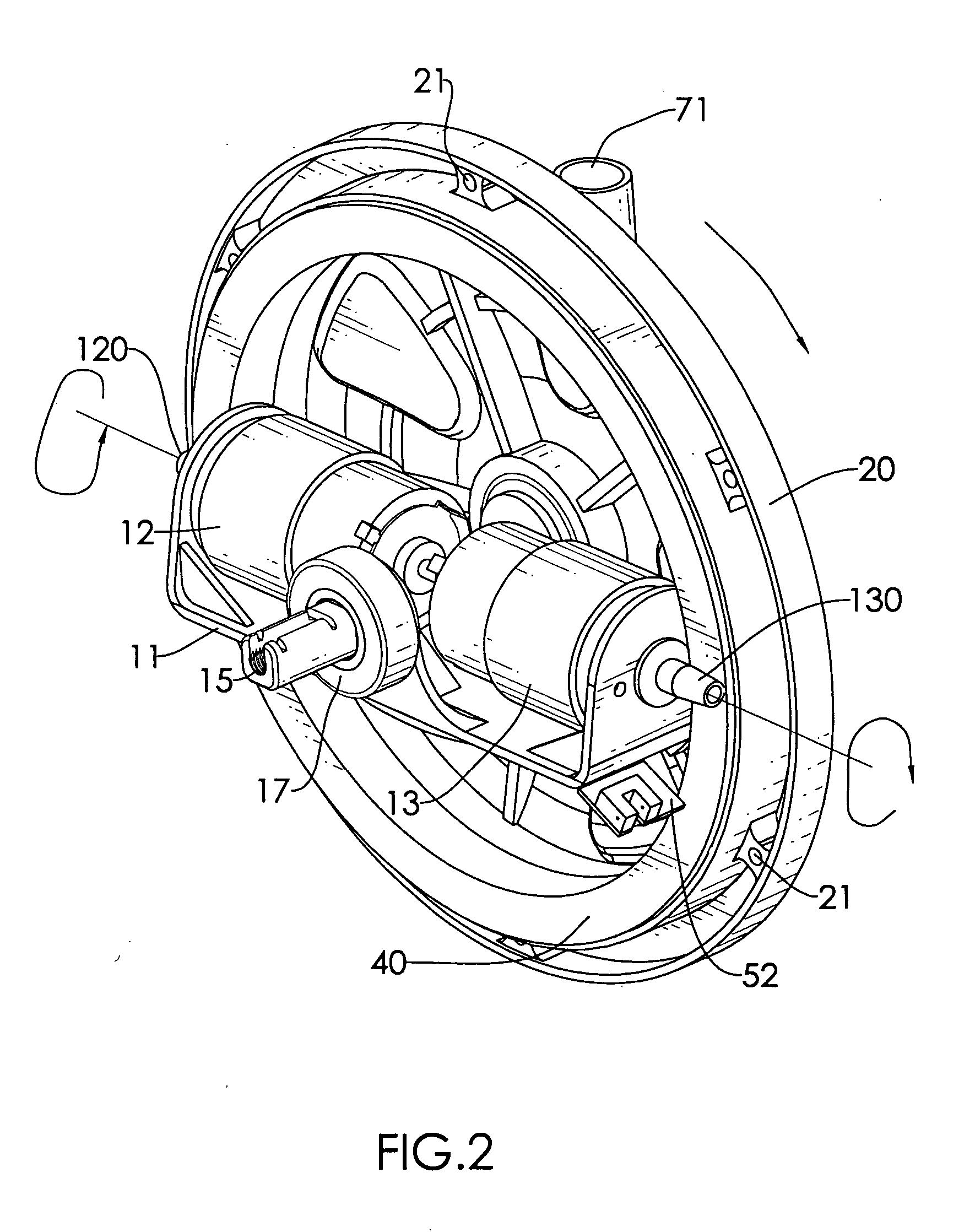
[0018] With reference to FIGS. 1 to 3, an electric wheel of the present invention mainly includes a transmission assembly (10), a left sidewall (20), a right sidewall (30), a wheel speed detecting device, a rubber tire (60) and a fork assembly.

[0019] The transmission assembly (10) includes a pair of motors (12)(13) mounted on a U-shaped base (11). The base (11) can be preferably made by a high-pressure extrusion or die casting process to form a bottom board, two upright walls extending from opposite ends of the bottom board, and two ears each of which projecting from the middle position at an edge of the bottom board. The motors (12)(13) are arranged in alignment with each other on the base (11) but rotate in opposite directions. Each motor (12)(13) has a spindle enclosed and protected by a spindle sleeve (120)(130) that projects through the upright wall of the base (11). Two axles (14)(15) each having a bearing (16)(17) mounted thereon are extended from the two ears of the base (1...


PUM


Abstract

An electric wheel has a transmission assembly and wheel speed detecting device mounted inside a chamber formed by two assembled sidewalls. A rubber tire surrounds the peripheries of the assembled sidewalls. Two hollow forks are respectively attached to external surfaces of the two sidewalls. A transmission ring is formed on an inner surface of one of the sidewalls and driven by the transmission assembly to rotate. As a result, the electric wheel is driven by the transmission ring and has rotating movements.

Description

BACKGROUND OF THE INVENTION [0001] 1. Field of the invention [0002] The invention relates to an electric wheel, and more particularly to a wheel suitable for use in light-duty devices, wherein motors are mounted inside the wheel as a power source to drive the wheel. [0003] 2. Related Art [0004] Varied useful means of transportation have been widely used and accepted in daily life. For example, supermarket trolleys, buggies, scooters or golf-bag trolleys are quite familiar to most people. [0005] Wheels are the most used elements in these transportation means and are usually driven by gears or belts fitted to an external transmission mechanism. However, high precision in alignment among different components required by the external transmission design is necessary. Further, using the external transmission mechanism may cause annoying noise and also leads the volume of the entire device to become unsatisfactorily bulky. [0006] For the above reasons, a novel electric wheel is proposed t...

Claims


Application Information

Patent Timeline
IPC IPC(8): B60K1/00
CPCB60K7/0007B60K17/043B60K2007/003B60K2007/0038B60K2007/0069B60L2220/46
Inventor TSENG, SIN-DUN
Owner TSENG SIN DUN
Learn More