Method of measuring decentering of lens

a lens and decentering technology, applied in the direction of instruments, optical axis determination, optical apparatus testing, etc., can solve the problems of complex three-dimensional position measuring apparatus, large time-consuming and labor-intensive measurement and data processing, and simple difference of aspherical surface shape error

Inactive Publication Date: 2006-09-21
CANON KK
View PDF8 Cites 15 Cited by
  • Summary
  • Abstract
  • Description
  • Claims
  • Application Information

AI Technical Summary

Benefits of technology

[0015] The present invention has as its object to provide a method of measuring the decentering of a lens which can measure the decentering of a curved surface axis from the measurement of a two-dimensional curved surface profile.

Problems solved by technology

This method, however, requires a complicated three-dimensional position measuring apparatus.
Also, as compared with two-dimensional profile measurement, the method includes a disadvantage that much time is required for measurement and data processing because enormous data is used.
If the coordinate axis of the optical axis of the design reference aspherical surface profile and the coordinate axis of the optical axis of the actually measured aspherical surface profile coincide with each other, a simple difference is an aspherical surface shape error.
In an ordinary case, however, due to the existence of the decentering component of the subject lens, the positional error, the inclination error, or the like when the subject lens is held on the measuring apparatus, the coordinate axis of the optical axis of the actually measured aspherical surface profile does not coincide with the optical axis of the design reference aspherical surface shape.
However, the decentering amount of the aspherical surface axis relative to the outer diameter of the subject lens could not be detected.
However, in the conventional two-dimensional profile measuring method, it has been difficult to measure the outer diameter position of the lens simultaneously with the measurement of the aspherical surface profile.

Method used


Image

  • Method of measuring decentering of lens
  • Method of measuring decentering of lens
  • Method of measuring decentering of lens

Examples


embodiment 1

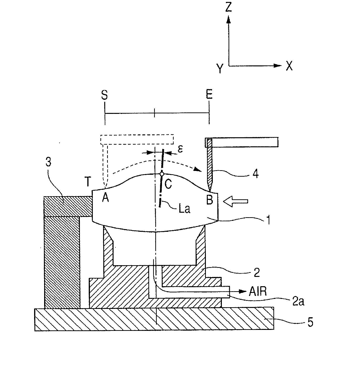
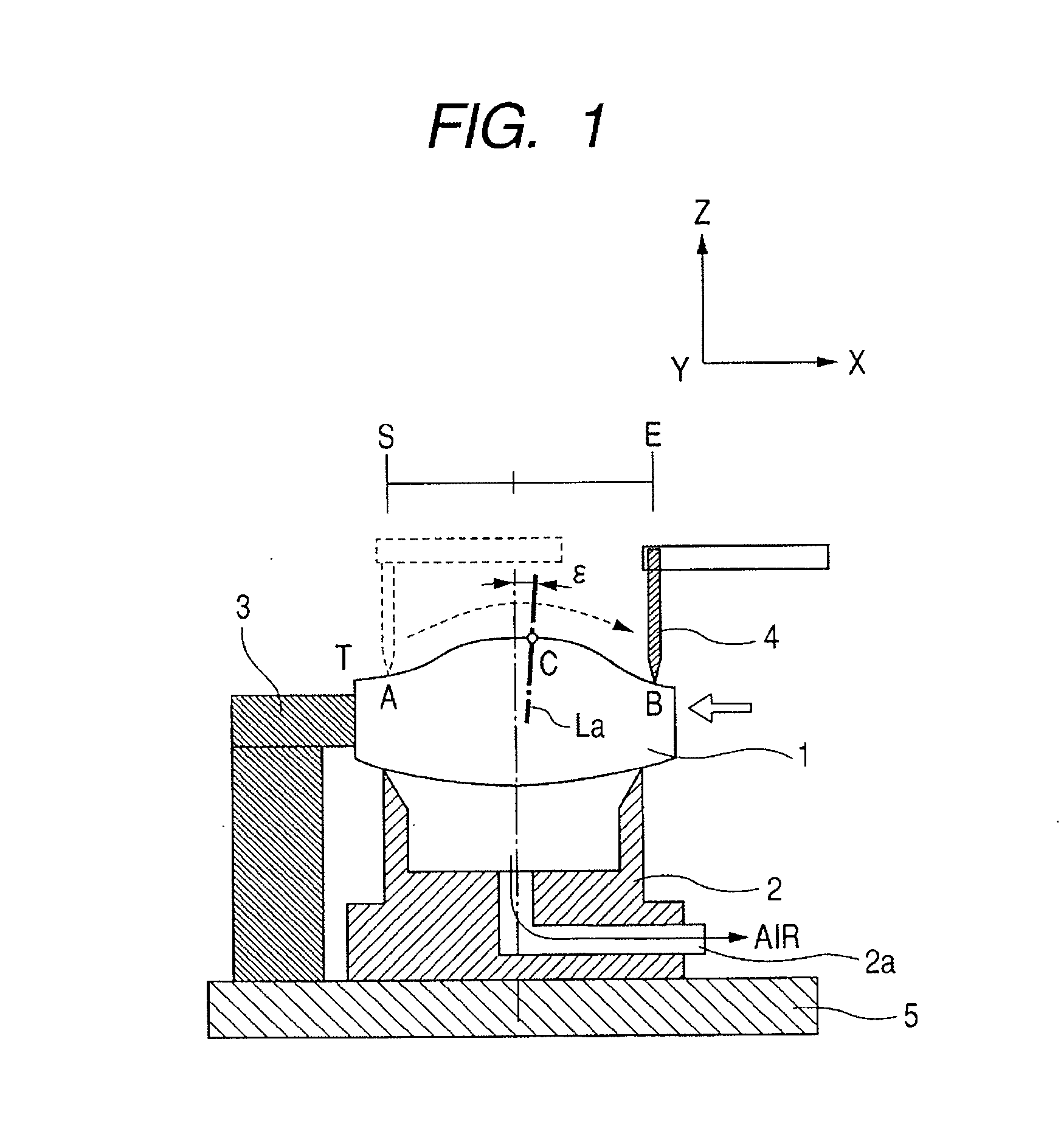
[0041]FIG. 1 is a schematic cross-sectional view of Embodiment 1 of the decentering measuring apparatus of the present invention. FIG. 5 is a perspective view of the essential portions of FIG. 1.

[0042] In FIG. 1, the reference numeral 1 designates a subject lens comprising a spherical lens or an aspherical lens. The reference numeral 2 denotes a receiving jig (lens holding member) for positioning of the subject lens 1 in the direction of the optical axis thereof. The reference numeral 3 designates a positioning jig for positioning of the subject lens 1 in directions perpendicular to the optical axis thereof (directions X and Y in FIG. 1). The reference numeral 4 denotes a probe (scanning member) for scanning on the surface of the subject lens 1 and measuring the surface profile thereof.

[0043] In FIG. 1, X-axis is defined as the coordinate system in the left to right direction in the plane of the drawing sheet, Y-axis is defined as the direction from this side to the inner part in t...

embodiment 2

[0111] Embodiment 2 of the present invention will now be described.

[0112] There is a case where it is desired to measure the decentering state of the aspherical surface axis of a subject lens of which the outer diameter portion is not subjected to centering processing. The subject lens before the centering processing is unstable in the dimensions of the outer diameter portion of the lens and therefore, cannot be subjected to such measurement as in Embodiment 1 with the outer diameter of the lens as the reference. Embodiment 2 is an embodiment for obtaining the decentering information of the subject lens before the centering processing.

[0113] In Embodiment 2, as shown in FIGS. 8 and 10, the subject lens 11 is fixed and held with the positions thereof in the direction of the optical axis and a direction perpendicular to the optical axis determined by a bell clamp method. FIG. 9 shows the state of the first measurement. FIG. 11 shows the state of the second measurement.

[0114]FIG. 12...


PUM


Abstract

Disclosed is a measuring method which can measure the decentering of an axis by the measurement of a two-dimensional curved surface profile. This method has a first step of measuring a profile of a examined surface by a probe from a first reference position which is a position separate by a predetermined amount from a predetermined position on the examined surface of a subject lens, a second step of measuring the profile of the examined surface by scanning the examined surface by the probe from the second reference position which is a position separate by a predetermined amount from said predetermined position in a route opposite to the scanning direction of said first step after a rotation of the subject lens; and the step of obtaining the decentering amount of the examined surface by the use of the measurement results obtained at the first and second steps.

Description

BACKGROUND OF THE INVENTION [0001] 1. Field of the Invention [0002] This invention relates to a method of measuring the decentering of a lens which is suitable for measuring the decentering amount of a curved surface, for example, the decentering amount of a spherical surface or an aspherical surface. [0003] 2. Related Background Art [0004] In recent years, in various optical systems for use in digital cameras, video cameras, etc., aspherical lenses are often adopted for an improvement in optical performance and the downsizing of the optical systems. [0005] Along with this, a method of accurately measuring the decentering amount of the optical axis (aspherical surface axis) of the aspherical lens is required. [0006] As a method of measuring the decentering amount of the aspherical surface axis of the aspherical lens, there is known a method of measuring the profile data of an aspherical lens by the use of a three-dimensional position measuring apparatus (Japanese Patent Application ...

Claims


Application Information

Patent Timeline
Patent Type & Authority Applications(United States)
IPC IPC(8): G01B9/00
CPCG01M11/0214G01M11/0221G01M11/025
Inventor MURATA, YASUNORI
Owner CANON KK
Why Eureka
Try Eureka