
Eureka
For R&D, Eureka makes reading and utilizing patents & technical documents easy.
Eureka AIR
Designed for self-driven R&D workflows. Generate viable solutions, solve complex R&D challenges, empower your innovation with AI.

Eureka Materials
Designed for material experts only. Revolutionize your material R&D, from search, analyze, to developing new materials.

TechResearch
Generate reliable direction feasibility study reports for your R&D in just a few steps.

TechSeek
Discover and master advanced knowledge NOW. Basics, ideas, possibilities, all at once.

TechMind
As an expert in R&D Theories, TechMind can generates customized viable solutions instantly.

TechRisk
Analyze your overall solution with one click, know your potential R&D risks in advance.

TechMonitor
Get weekly tech updates, stay abreast of the latest tech innovations and key insights.
Image processing apparatus, method and program
- Summary
- Abstract
- Description
- Claims
- Application Information
AI Technical Summary
Benefits of technology
Problems solved by technology
Method used
Image

Examples
first embodiment
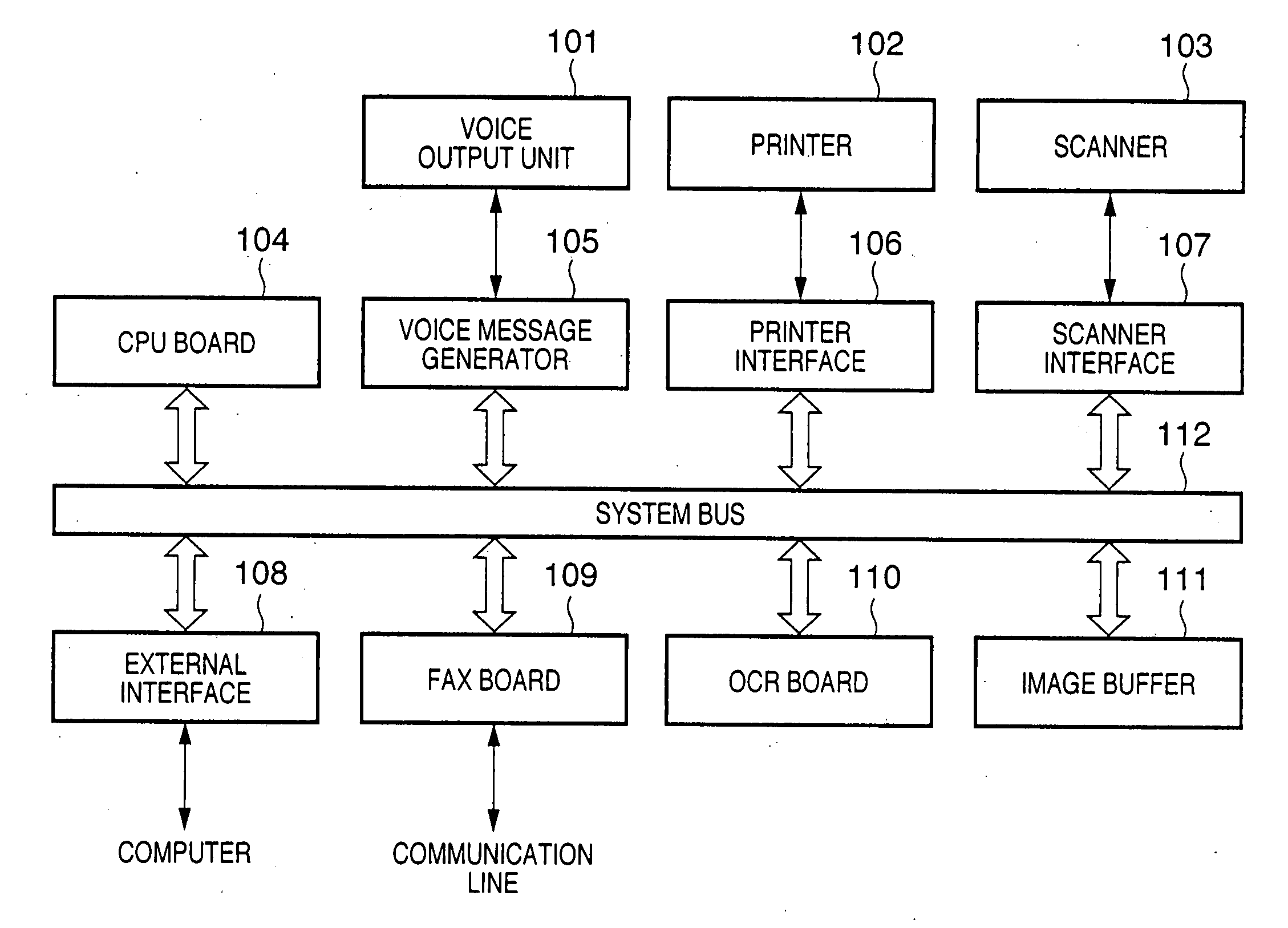
[0025]FIG. 1 is a block diagram illustrating the structure of an image processing apparatus according to the present invention. The apparatus includes a voice output unit 101 such as a speaker for outputting a message produced by a voice message generator 105. The generation of the voice message in the voice message generator 105 employs a well-known technique such as a speech synthesis method of the kind disclosed in the specification of Japanese Patent Application Laid-Open No. 3-149600. The apparatus further includes a printer 102, such as a laser printer or ink-jet printer, which is connected via a printer interface 106.
[0026] The printer interface 106 controls the printer 102 and performs control for interfacing data with an external device. A scanner 103 is connected via a scanner interface 107. Image data that has been read in from the scanner 103 is stored in an image buffer 111.
[0027] The apparatus further includes a CPU board 104 having a function for controlling the ove...
second embodiment
[0046] An image processing apparatus according to a second embodiment of the present invention. In the first embodiment, it is assumed that a single settings form is included in documents set in the apparatus at one time. However, it is also possible to include a plurality of settings forms (901, 902), as shown in FIG. 9. A flowchart for executing this operation is illustrated in FIG. 11 taking a copier as an example.
[0047] If a start button is pressed to start processing (step S1101) and it is determined that a document has been placed on the platen (“YES” at step S1102), the document image is read in by the scanner 103 (step S1103) and the read image is transmitted to the OCR 110 (step S1105).
[0048] If no document has been placed on the platen (“NO” at step S1102), then processing is exited (step S1104). If a result of recognition is received from the OCR 110 (“YES” at step S1106), it is determined from this result whether the document is one for configuring the apparatus (step ...
third embodiment
[0057] The first and second embodiments have been illustrated taking a copier as an example. However, it is possible to perform operation in a similar manner also with regard to the configuring of an apparatus when a document is transmitted by facsimile or e-mail. In such case the destination of the facsimile transmission or the address of the e-mail transmission would be set not by pressing a button provided on the apparatus but by filling in the destination or address on a settings form in advance, thereby making it possible to configure the apparatus simply.
PUM
 Abstract
Description
Claims
Application Information
 - R&D Engineer
- R&D Manager
- IP Professional
- Industry Leading Data Capabilities
- Powerful AI technology
- Patent DNA Extraction
Browse by: Latest US Patents, China's latest patents, Technical Efficacy Thesaurus, Application Domain, Technology Topic, Popular Technical Reports.
© 2024 PatSnap. All rights reserved.Legal|Privacy policy|Modern Slavery Act Transparency Statement|Sitemap|About US| Contact US: help@patsnap.com