Auto-servo tape system and associated recording head

a technology of auto-servo tape and associated recording head, which is applied in the direction of maintaining head carrier alignment, digital recording, instruments, etc., can solve the problems of static shift, unstable ltm, and increased tape exposure,

Active Publication Date: 2006-09-21
QUANTUM CORP
View PDF99 Cites 23 Cited by
  • Summary
  • Abstract
  • Description
  • Claims
  • Application Information

AI Technical Summary

Benefits of technology

[0014] The second write element is operable to write a first reference track that partially overwrites the first data track to create a reference edge while the first write element writes the first data track. The lateral offset between the second read and write elements is based upon a width of the first data track less a portion of the lateral width of the second read element overlapping the first reference track when the head is properly positioned with respect to a next data track. The head is operable to write the first data track on magnetic tape so that the first data track width is less than 1.0 micron, and may be even less than 0.6 microns.

Problems solved by technology

The tape therefore becomes more susceptible to errors caused from the tape shifting up or down (called lateral tape motion or “LTM”) in a direction perpendicular to the tape travel path as the tape passes by the magnetic head.
Some may cause abrupt momentary jumps while others may cause a static shift.
Generally, LTM is unpredictable and unrepeatable.
In multi-head, multi-channel magnetic tape storage systems, random lateral tape motion is generally a limiting factor in achieving higher track densities, and thus higher user data capacity.
Mis-registration between the head and data tracks can cause data errors during readback, and data loss on adjacent tracks during writing.
One disadvantage of prewritten servo tracks is that the use of a separate servo track writer introduces errors into the system, reducing the ability to obtain the smallest track width.

Method used


Image

  • Auto-servo tape system and associated recording head
  • Auto-servo tape system and associated recording head
  • Auto-servo tape system and associated recording head

Examples


Embodiment Construction

[0023] The following description is presented to enable a person of ordinary skill in the art to make and use the invention. Descriptions of specific devices, techniques, and applications are provided only as examples. Various modifications to the examples described herein will be readily apparent to those of ordinary skill in the art, and the general principles defined herein may be applied to other examples and applications without departing from the spirit and scope of the invention. Thus, the present invention is not intended to be limited to the examples described herein and shown, but is to be accorded the scope consistent with the claims.

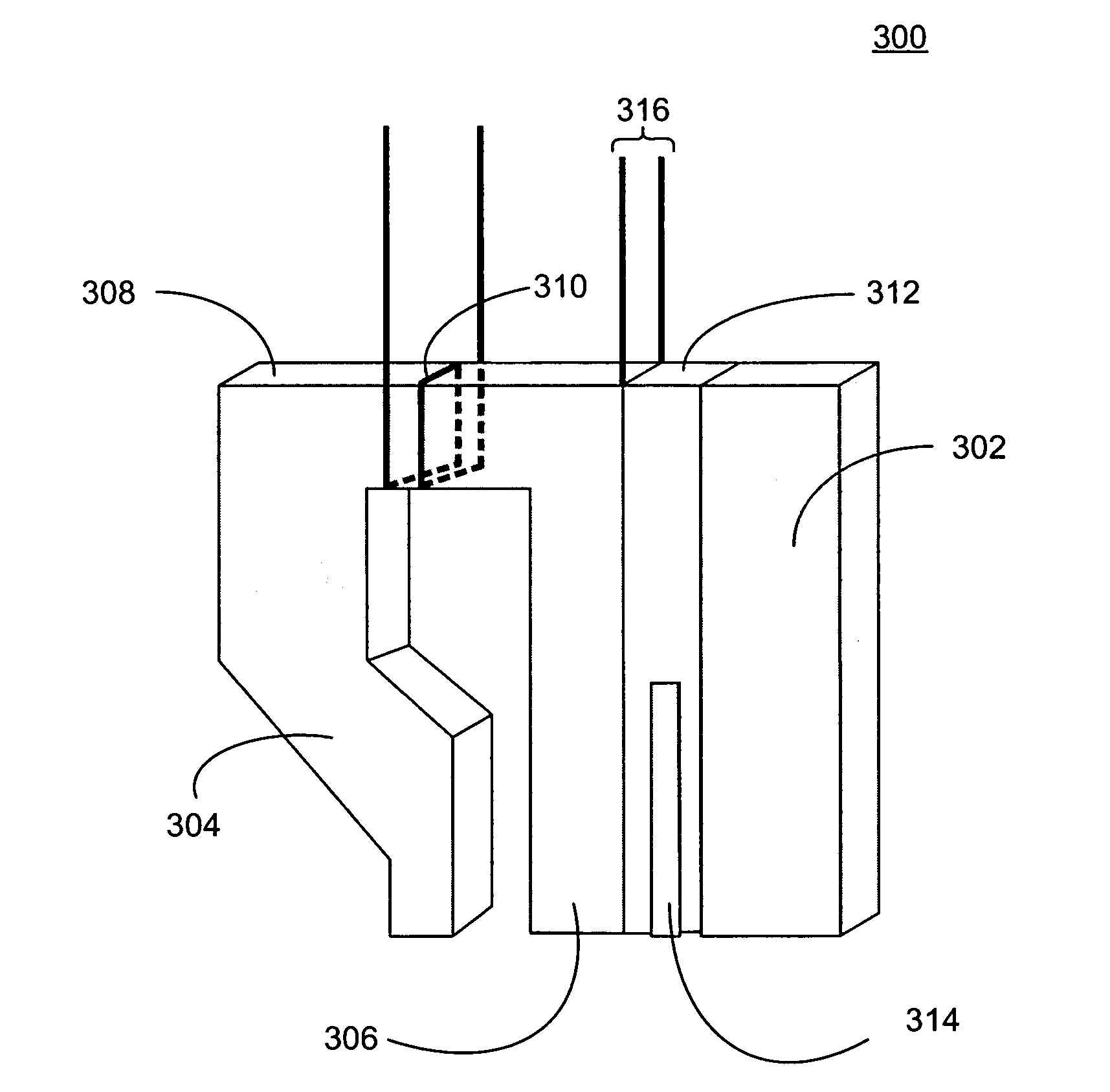
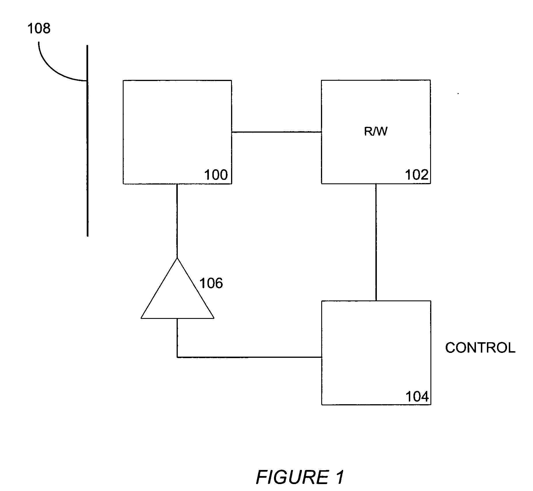
[0024]FIG. 1 illustrates a servo system according to an embodiment of the present invention, which may be implemented in a media drive, such as a tape drive, for example. The system includes a read / write head assembly 100 according to an embodiment of the invention, read / write electronics 102 for respectively reading and writing signals from...


PUM

PropertyMeasurementUnit
widthaaaaaaaaaa
widthaaaaaaaaaa
widthaaaaaaaaaa

Abstract

A recording head comprises a first tape-head contact area including a first write element and a first read element, which itself may include an MR sensor element. The first read element is laterally offset as to the first write element, and no portion of the first read element lies in a region laterally overlapped by the first write element. A second tape-head contact area includes a second write element and a second read element, which also may include an MR sensor element. The second read element is laterally offset as to the second write element, and no portion of the second read element lies in a region laterally overlapped by the second write element. The first read and write elements of the first tape-head contact area are aligned with the second write and read elements of the second tape-head contact area so that an end portion of the second write element lies in a region that laterally overlaps only an end portion of the first write element. Data track widths less than one micron are achievable with this head design.

Description

BACKGROUND OF THE INVENTION [0001] 1. Field of the Invention [0002] The present invention generally relates to storage devices, and more particularly to servo systems for compensating for lateral tape motion. [0003] 2. Related Art [0004] Increased data storage capacity and retrieval performance are desired of all commercially viable mass storage devices and media. In the case of linear tape recording, a popular trend is toward multi-head, multi-channel head structures with narrowed recording gaps and data track widths, so that many linear data tracks may be laid on a tape medium of a predetermined width, such as one-half inch width tape. To increase the storage density for a given cartridge size, the bits on the tape may be written to smaller areas and on a plurality of parallel longitudinal tracks. As more data tracks are recorded on a tape, each track becomes increasingly narrow. The tape therefore becomes more susceptible to errors caused from the tape shifting up or down (called...

Claims


Application Information

Patent Timeline
Patent Type & Authority Applications(United States)
IPC IPC(8): G11B21/02
CPCG11B5/00826G11B5/584
Inventor SALIBA, GEORGE A.
Owner QUANTUM CORP
Why Eureka
Try Eureka