Loudspeaker rigging system having contained maneuverable connecting links

a technology of connecting links and loudspeakers, which is applied in the direction of transducer details, electrical transducers, electrical apparatus casings/cabinets/drawers, etc., can solve the problems of large number of pinning locations, large number of holes, and relatively difficult process, and achieves small incremental splay angle adjustment capabilities, easy assembly, and easy maneuverability

Active Publication Date: 2006-09-21
MEYER SOUND LABORATORIES
View PDF16 Cites 28 Cited by
  • Summary
  • Abstract
  • Description
  • Claims
  • Application Information

AI Technical Summary

Benefits of technology

[0006] There is a need for a rigging system for loudspeakers having links the are easily maneuvered in the rigging frame and that will can not drop out of the frame. T

Problems solved by technology

This process turns out to be relatively difficult and leads to misses in the hole alignment while assembling the array.
The number of pinning locations is also relatively limited.
Another problems associated with rigging systems involves the difficult

Method used


Image

  • Loudspeaker rigging system having contained maneuverable connecting links
  • Loudspeaker rigging system having contained maneuverable connecting links
  • Loudspeaker rigging system having contained maneuverable connecting links

Examples


Embodiment Construction

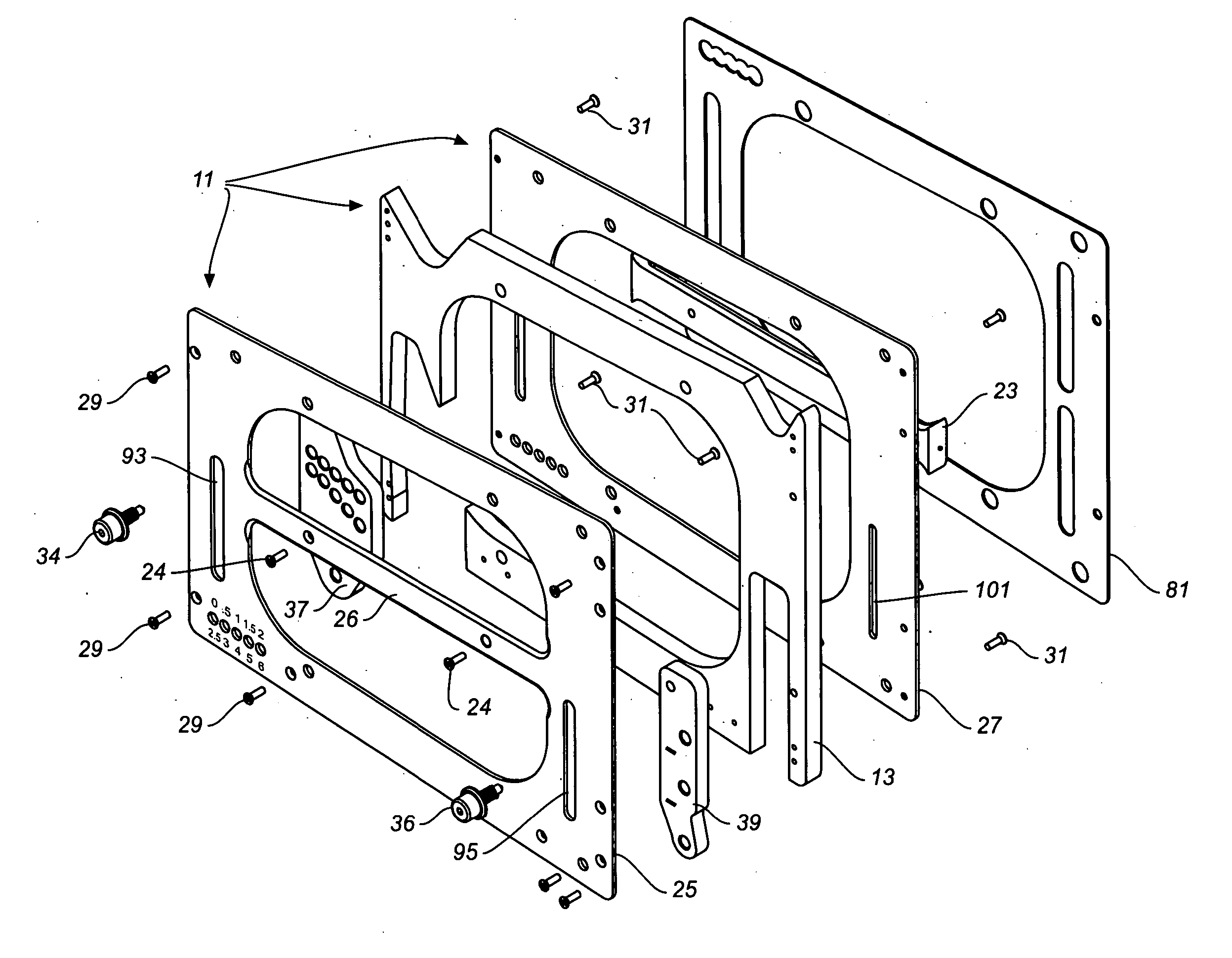
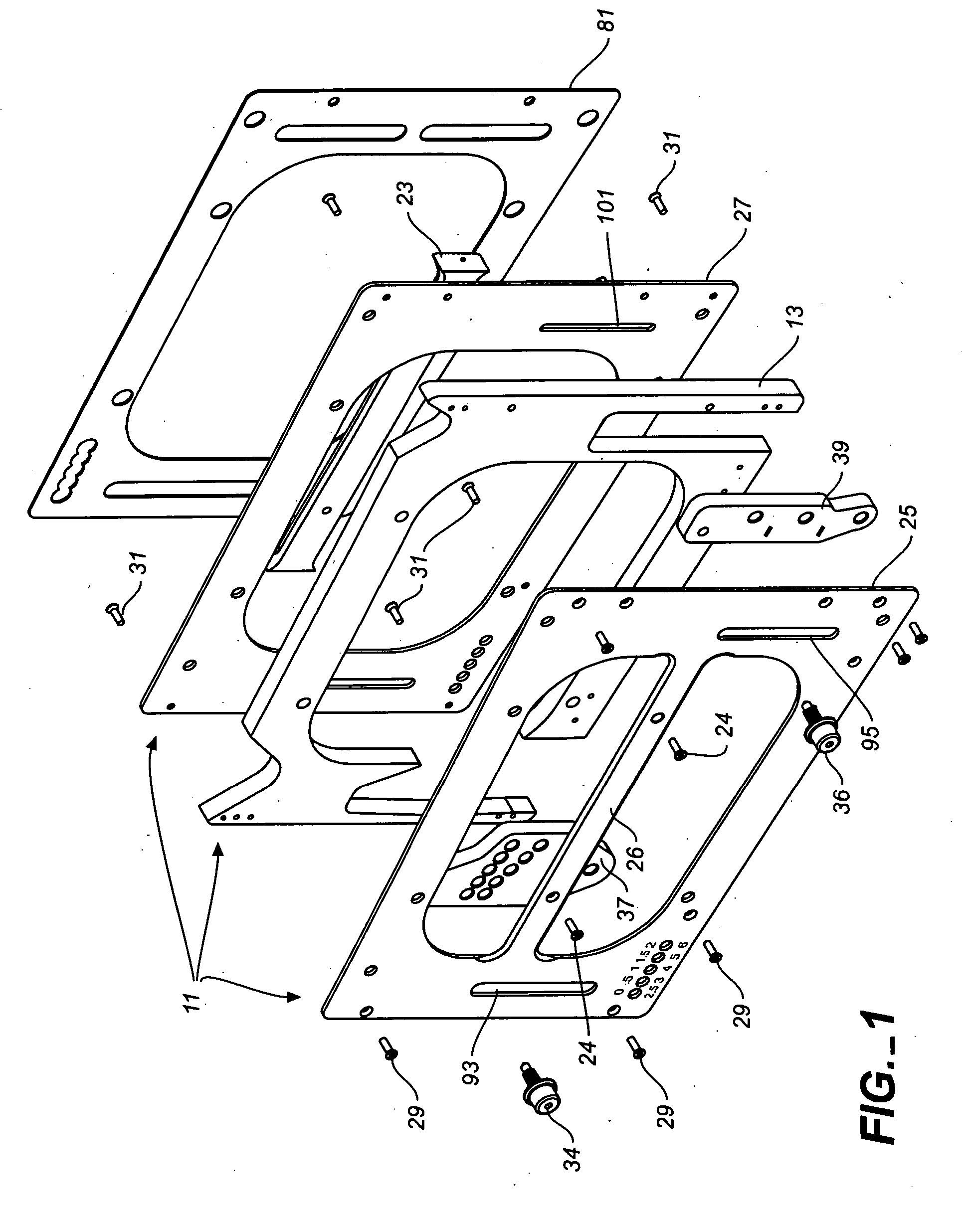
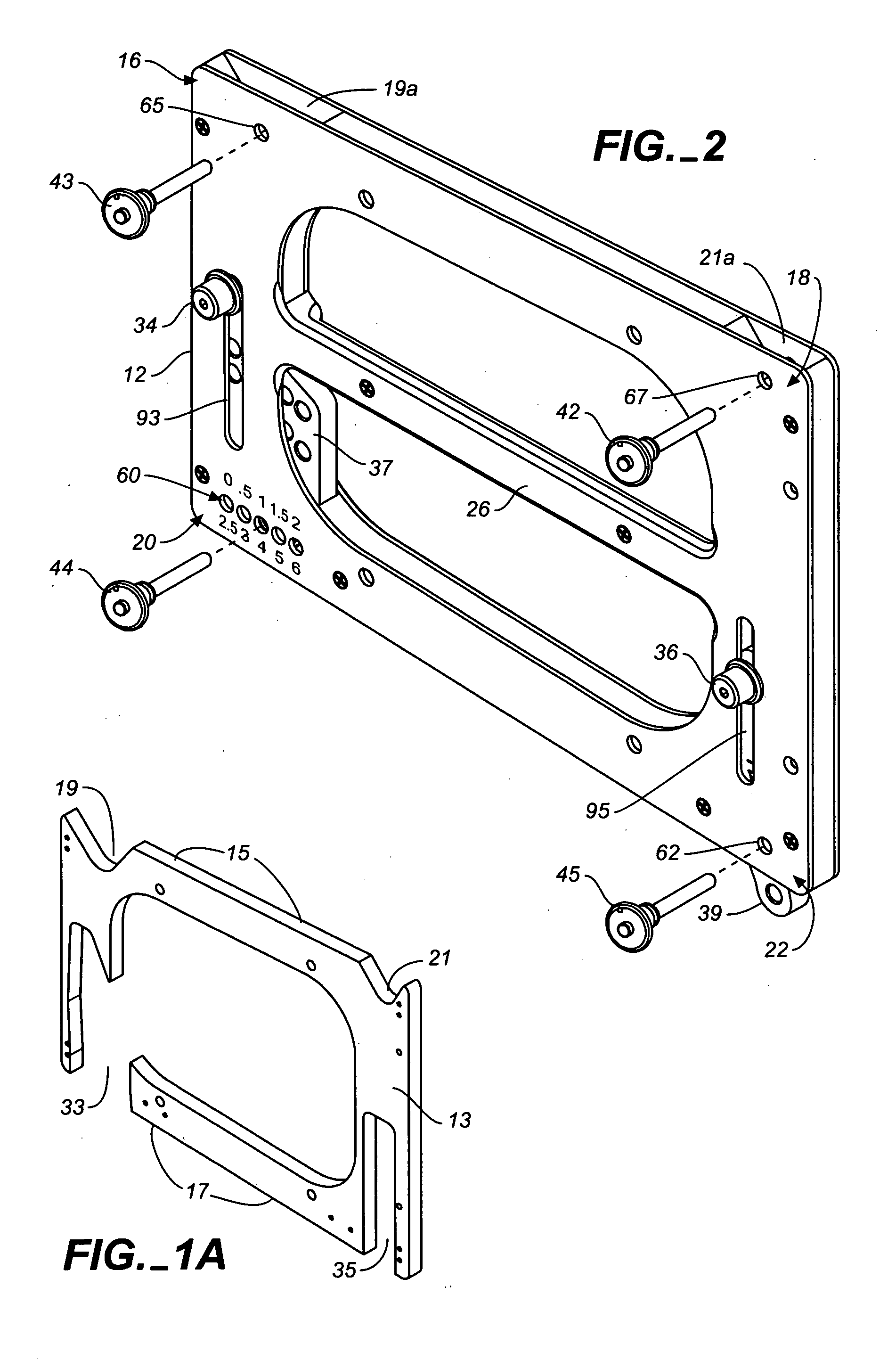
[0027] The preferred assembly construction of the rigging side frame of the invention is disclosed in FIGS. 1, 1A, and 1B. The rigging side frame is comprised of a frame assembly denoted by the numeral 11 having a center core 13 with an top edge portion 15. As best shown in FIGS. 1A and 1B, the top edge portion of the center core includes two cutouts 19, 21, which form seating surfaces 63, 75 for link guide channels of the assembled frame as hereinafter described. The center core of the assembly is sandwiched between front and back side plates 25, 27 that are secured to the center core sections by suitable front and back attachment screws 29, 31. As later described, when assembled, the open regions 33, 35 in the core's bottom edge portion 17, form additional guide channels 33a and 35a for stowing frame connecting links associated with the side frame, namely, splay adjustment link 37 and pivot link 39. A gripping knob 34, 36 associated with each connecting link is provided for maneuv...


PUM


Abstract

A side frame for a loudspeaker rigging system has a frame structure mountable to the side of a loudspeaker, and links associated with the frame structure for linking together the corners of the frame structures of vertically adjacent side frames. The links associated with each side frame structure include a pivot link and splay adjustment link, each of which has a top extended end and a base end. Stow channels, which are preferably located in the bottom corner regions of the frame structure, contain the pivot link and splay adjustment link in the frame structure. A gripping structure associated with at least one, and preferably each link of the pivot and splay adjustment links allows a user to easily maneuver a link from its stowed to its deployed position. The extended end of the splay adjustment link includes at least two, and preferably an array of pin holes which can selectively be matched with one pin hole within a row of pin holes in a bottom corner region of the side frame to permit adjustments of the splay angle over a range of angles. Suitably, two rows of pin holes are provided in the top extended end of the splay adjustment link to permit multiple and incrementally small splay angle adjustments. In the preferred embodiment, the frame structure is comprised of an assembly of parts comprised of a center core structure sandwiched between two side plates.

Description

CROSS-REFERENCE TO RELATED APPLICATIONS [0001] This application claims the benefit of U.S. Provisional Application No. 60 / 669,176, filed Apr. 6, 2005, and is a continuation-in-part of U.S. application Ser. No. 11 / 035,676 filed Jan. 13, 2005, now pending, which claims the benefit of U.S. Provisional Application No. 60 / 536,429 filed Jan. 13, 2004, and U.S. Provisional Application No. 60 / 548,364 filed Feb. 27, 2004.BACKGROUND [0002] The present invention relates to loudspeaker rigging systems and more particularly to rigging hardware for suspending a stacked array of loudspeakers of a sound reinforcement system at a predetermined location relative to an audience. The present invention has particular application in rigging a stacked array of loudspeakers wherein a vertical splay between loudspeakers is desired to achieve a desired coverage and acoustic performance. [0003] Sound systems for large venues typically involve the suspension or “flying” of stacks of loudspeakers in vertical ar...

Claims


Application Information

Patent Timeline
IPC IPC(8): H04R1/02H05K5/00
CPCH04R1/028H04R1/403H04R2499/13
Inventor MONITTO, JOHNMCGHEE, JOHNMARSHALL, DEAN
Owner MEYER SOUND LABORATORIES
Why Eureka
Try Eureka