Object detector for a vehicle

Inactive Publication Date: 2006-09-21
ORMON CORP
View PDF1 Cites 9 Cited by
  • Summary
  • Abstract
  • Description
  • Claims
  • Application Information

AI Technical Summary

Benefits of technology

[0013] It is therefore an object of this invention to provide an improved on-vehicle object detector capable of correctly detecting a front going vehicle relative to a road signs or the

Problems solved by technology

When a road sign is present above the traffic lane, however, a conventional device of the type described above can measure its distance but cannot determine whether it is a road sign of a vehicle (or an obstacle that has fallen onto the road surface).
If the reflecting object is a large truck having a width about equal to that of a road sign and especially in the case of an aluminum van with a high reflectivity, however, the number of detection points becomes large and it becomes difficult by this method to co

Method used


Image

  • Object detector for a vehicle
  • Object detector for a vehicle
  • Object detector for a vehicle

Examples


Embodiment Construction

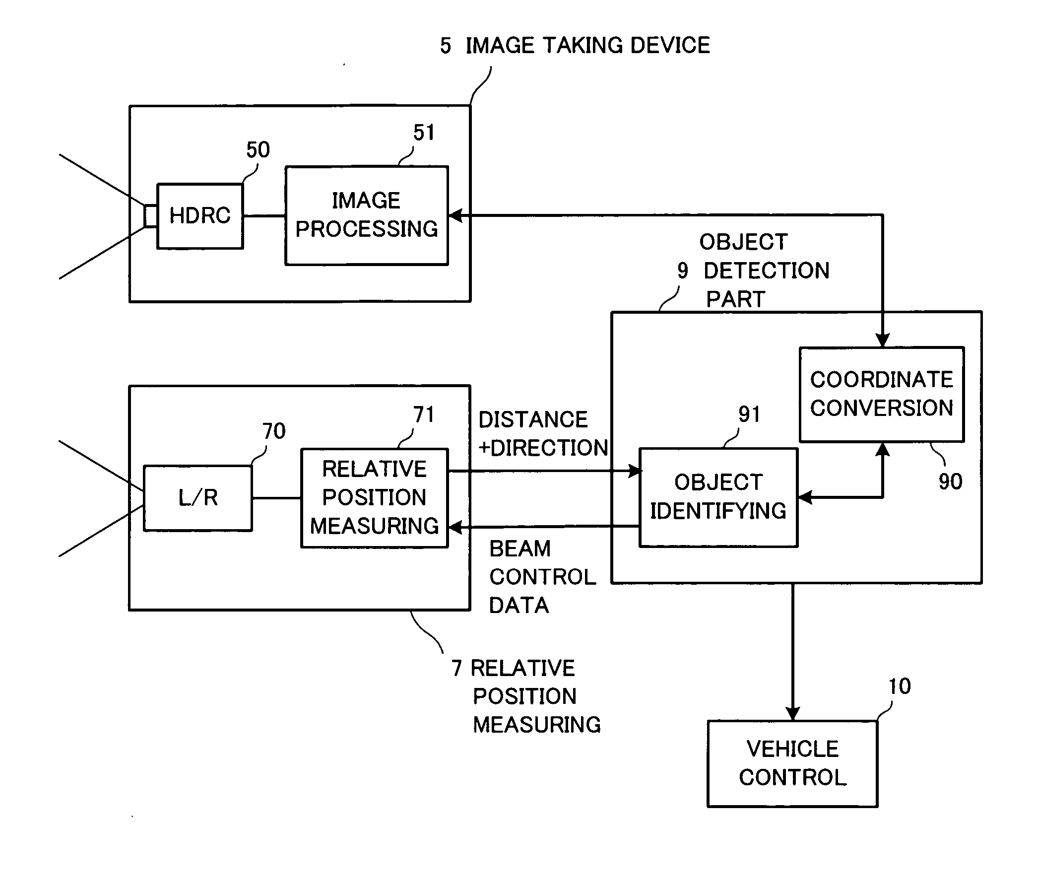
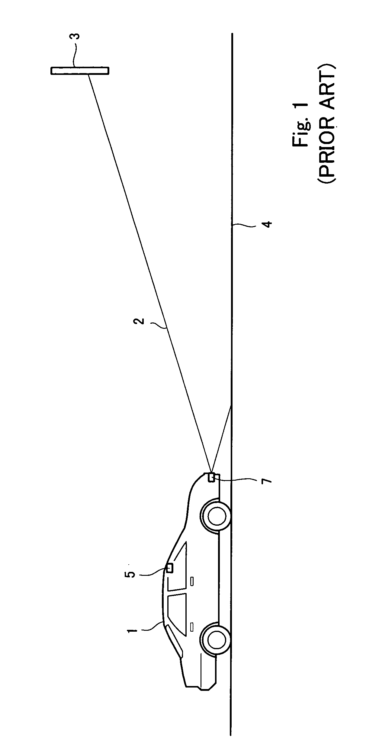
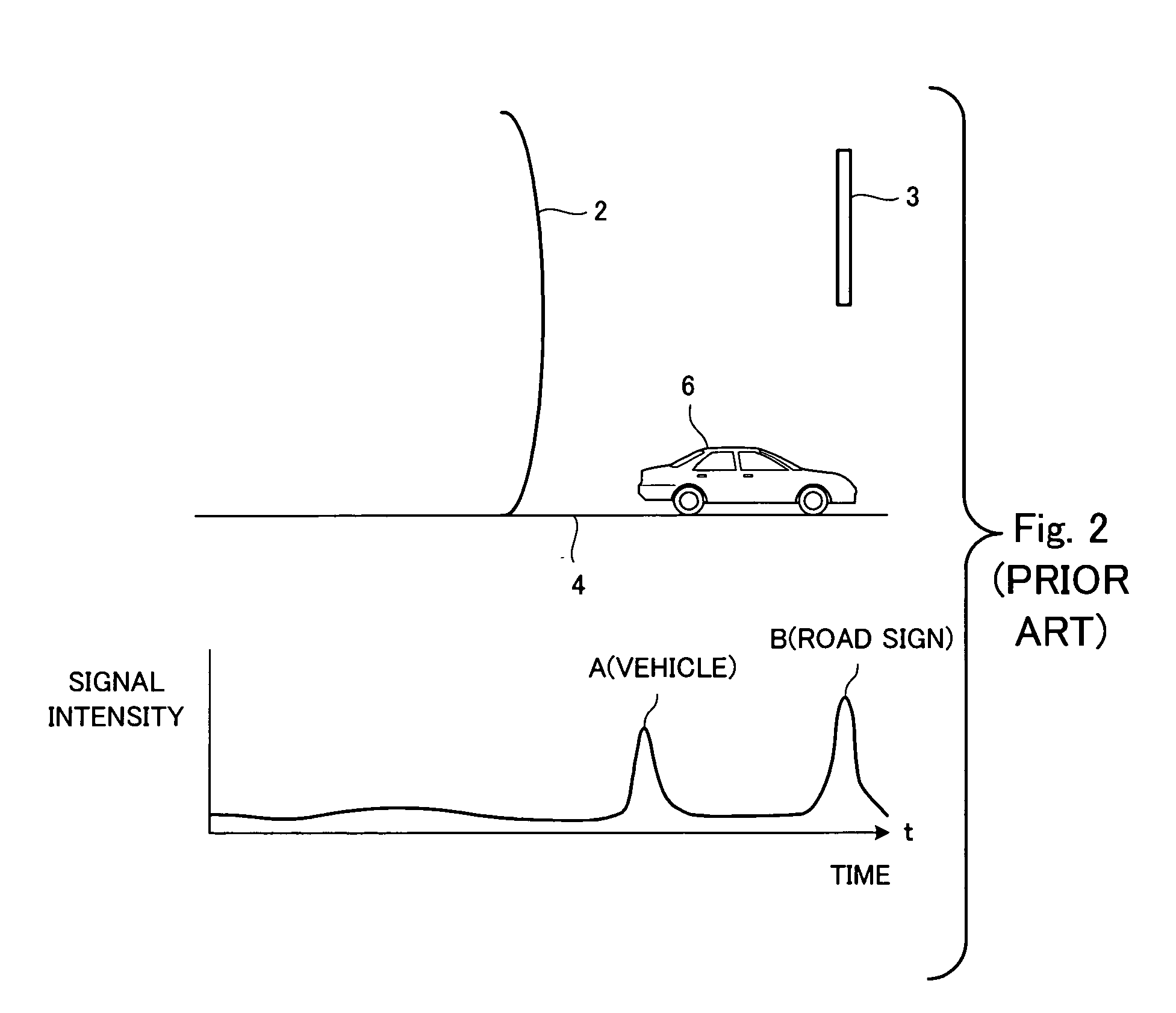
[0032]FIG. 5 (wherein like components are indicated by the same numerals as used and explained above) shows the positional relationship between a vehicle (the own vehicle) provided with an on-vehicle object detector embodying this invention and a front going vehicle 6. As shown schematically, the on-vehicle object detector according to this embodiment of the invention is comprised of a relative position measuring device 7 and an image-taking device 5. The relative position measuring device 7 includes a near infrared laser radar (hereinafter referred to as L / R) for emitting a near infrared laser beam (detection beam) 2 forward to measure the distance to an object that reflects it and the relative position of the beam-reflecting object based on the beam direction data. The image-taking device 5 includes a cameral for taking the image in front of the vehicle (the own vehicle) to which it is installed. If a CMOS camera with a high dynamic range (herein referred to as an HDRC) is used, a...


PUM


Abstract

An on-vehicle object detector has both a relative position measuring device and an image-taking device. The relative position measuring device is for scanning a frontal area with a beam of electromagnetic waves and measures distance L1 and direction to an object that reflects the waves. The image-taking device is for obtaining an image above a traffic lane in front and measures distance L2 to an object detected on this image. The vertical angle of spread of the electromagnetic beam is reduced if it is indicated by these devices that there is an object for which |L1-L2| satisfies a specified condition, indicating that there is an overhead road sign which is likely to affect the accuracy of measurement.

Description

[0001] Priority is claimed on Japanese Patent Application 2005-073683 filed Mar. 15, 2005. BACKGROUND OF THE INVENTION [0002] This invention relates to a device for detecting the relative position of an object that may be present in front by scanning the frontal area by an electromagnetic beam and more particularly to an on-vehicle object detector adapted to eliminate error in measuring a distance especially in the presence of an object such as a road sign plate or the like (hereinafter referred to as a road sign) above the traffic lane. [0003] Devices using an electromagnetic radar beam to scan an frontal area and measuring the time for reflected beam to return to calculate the distance to an object that may be present in front are coming to be installed to mobile bodies and especially to motor vehicles for a traffic control. If the object reflecting the beam is another vehicle, the measured results can be used for controlling the speed of one's own vehicle. If a two-dimensional be...

Claims


Application Information

Patent Timeline
IPC IPC(8): G06K9/00G01C21/00G01S13/931G01S17/86
CPCG01S13/86G01S13/931G01S2013/9357G01S2013/9375G01S17/023G01S2013/9325G01S2013/9321G01S7/4972G01S13/723G01S13/867G01S2013/9323G01S2013/9322G01S2013/93271G01S17/86G01S7/4034G01S7/4026
Inventor FUJIOKA, RYOJIANDO, TANICHI
Owner ORMON CORP
Why Eureka
Try Eureka