
Integrated duct and monitor housing

Inactive Publication Date: 2006-09-21
DEERE & CO
View PDF26 Cites 9 Cited by
  • Summary
  • Abstract
  • Description
  • Claims
  • Application Information

AI Technical Summary

Benefits of technology

[0004] As indicated above, much of the prior art combines air flow channels, i.e., air ducts, with the mounting structure. Such an arrangement tends to save space. However, in each case, space and cost is increased by the larger and more complex mounting structures that are separate from the duct structure. These arrangements tend to result in greater space requirements and costs due to the greater amount of material and complexity involved in the design of separate structures. Described and herein is an integrated duct and monitor housing that is hollow throughout its structure and provides monitor attachment points only at specific points on the ductwork. This tends to save space and reduce costs as no large plenum areas or separate mounting structures are required and air moves quickly through the structure with a minimum loss of energy to the materials of the housing.

Problems solved by technology

Such an arrangement tends to save space.
However, in each case, space and cost is increased by the larger and more complex mounting structures that are separate from the duct structure.
These arrangements tend to result in greater space requirements and costs due to the greater amount of material and complexity involved in the design of separate structures.

Method used


Image

  • Integrated duct and monitor housing
  • Integrated duct and monitor housing
  • Integrated duct and monitor housing

Examples


Embodiment Construction

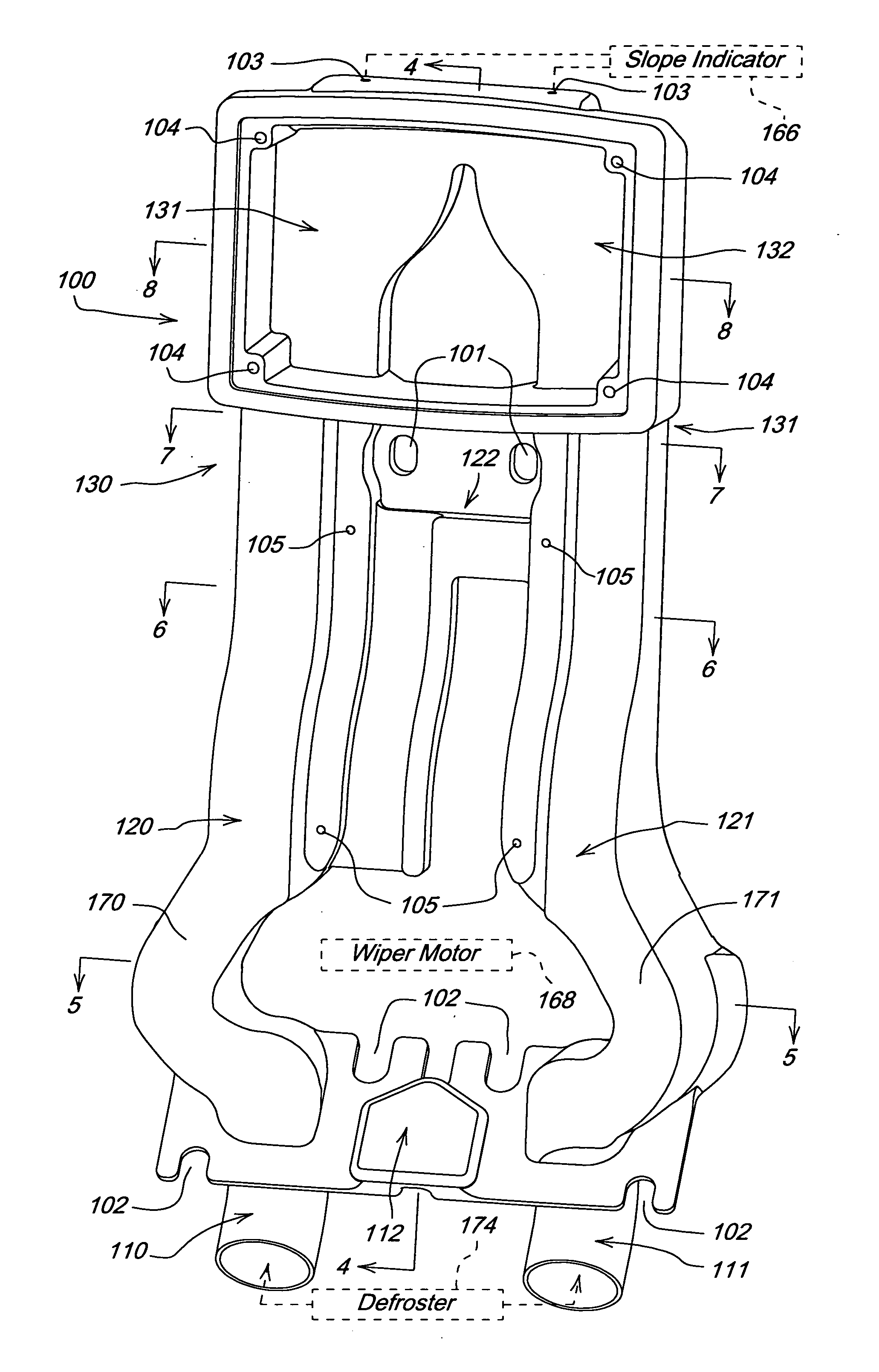
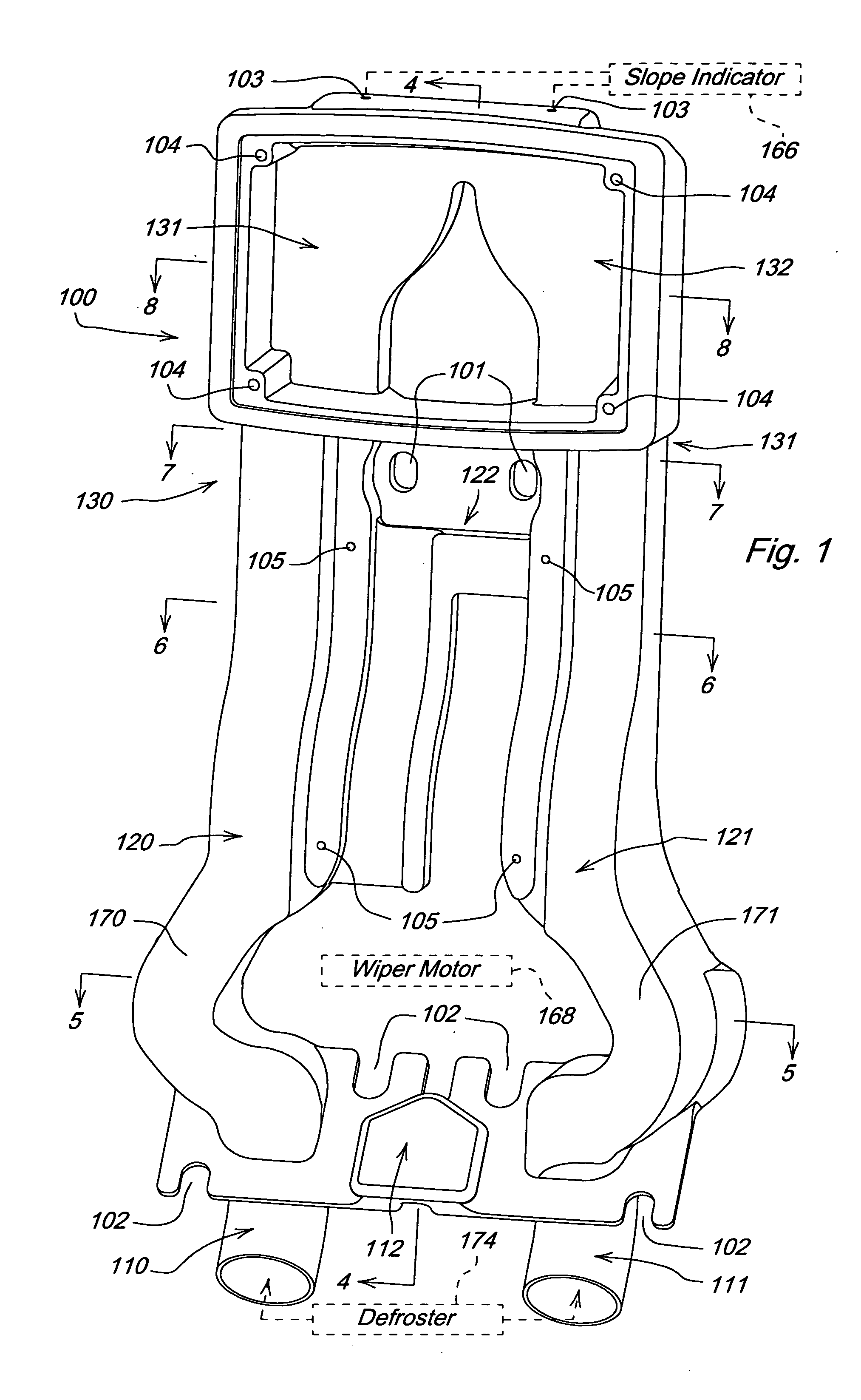
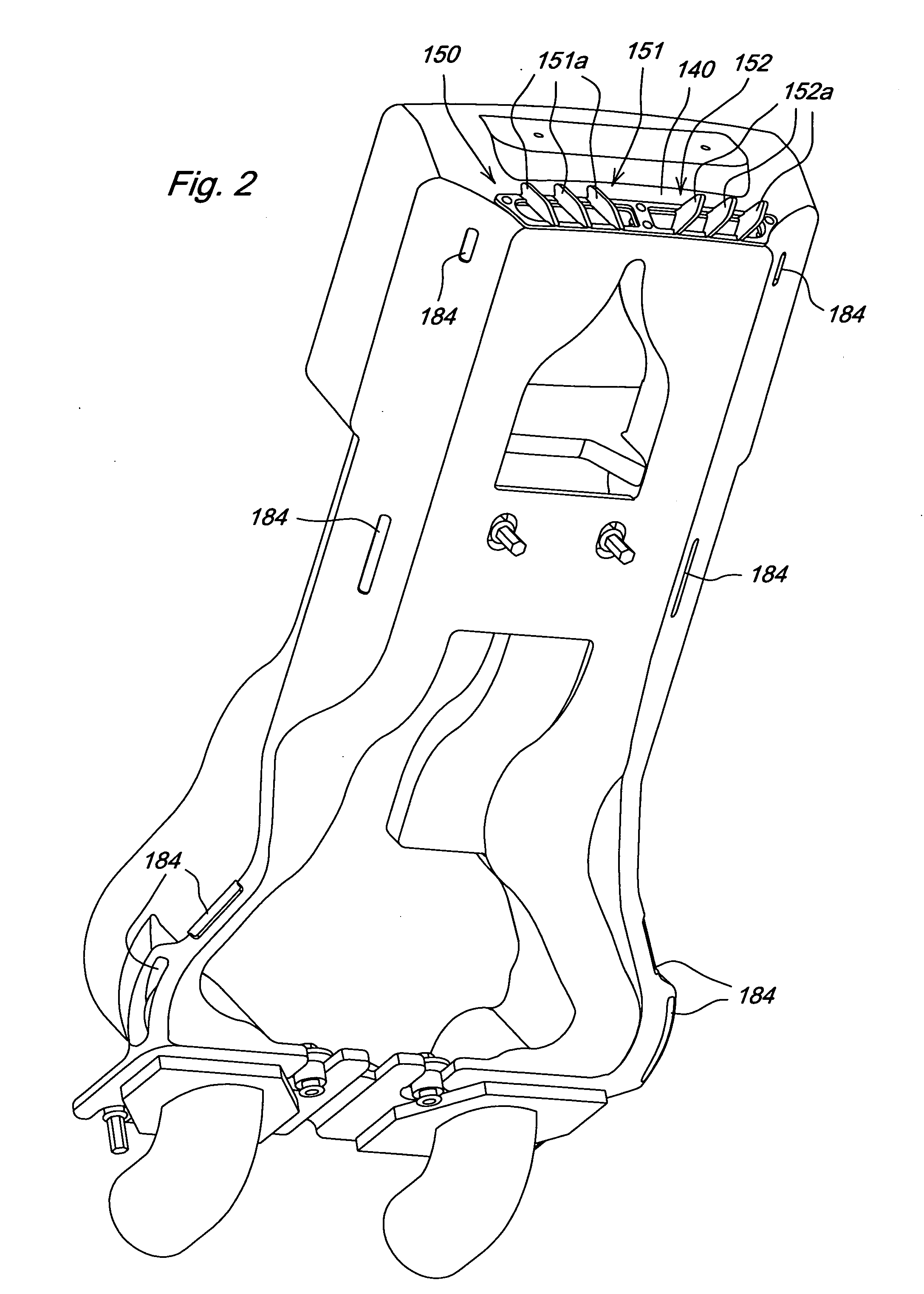
[0014]FIGS. 1 and 2 illustrate an exemplary embodiment of an integrated duct and monitor housing 100 of the invention for a construction vehicle such as, for example, a motor grader. The integrated duct and monitor housing 100 includes: air inlets 110 and 111; a first small mounting structure 112; second and third duct portions 120 and 121; a second mounting structure 122; fourth and fifth duct portions 130 and 131; a third mounting structure 132; and air outlets 151 and 152 formed in an air outlet cover or louver 150 and configured as air vents with air vanes 151a and 152a. The integrated duct and monitor housing 100 is hollow throughout; air flows throughout its structure.

[0015] Mounting holes 101 and mounting slots 102 of the first and second mounting structures 112 and 122 are for the purpose of anchoring the integrated duct and monitor housing 100 to a portion of the structure of the vehicle (not shown). The first and second mounting structures 112 and 122 thus provide, alone ...


PUM


Abstract

An integrated duct and monitor housing having ductwork for environmental control via the flow of air and mounting provisions for a monitor. The entire arrangement is suitable for use in a vehicle. The housing includes an air inlet a housing mounting structure for anchoring the housing to a portion of a structure; a monitor mounting structure for anchoring a monitor to the housing and an air outlet. The air inlet, the housing monitor structure, the monitor mounting structure, the monitor mounting structure, and the air outlet form an integrated housing, the integrated housing being hollow throughout and allowing air flow throughout the housing.

Description

[0001] This application claims the benefit under 35 U.S.C. §119(e) of U.S. Provisional Patent Application No. 60 / 659,329 which was filed 7 Mar. 2005 and is hereby incorporated by reference herein.FIELD OF THE INVENTION [0002] The invention relates to housings and, more particularly, relates to monitor housings with integrated ducts for environmental control, particularly for heavy machinery such as, for example, motor graders. BACKGROUND OF THE INVENTION [0003] Various types of monitor housings exist for heavy, off road equipment. Much of the prior art includes multiple sets of distribution ducts with separate instrument housing, specially designed duct housing separate from any instrument housing, or integrated duct housing with large plenum areas as well as large mounting areas, separate from the air flow channels, where one or more instruments or instrument panels may be mounted. SUMMARY OF THE INVENTION [0004] As indicated above, much of the prior art combines air flow channels,...

Claims


Application Information

Patent Timeline
IPC IPC(8): B60H1/00
CPCB60H1/00378B60H1/00564B60H1/242
Inventor HACHMANN, ROBERT JOSEPH
Owner DEERE & CO
Learn More