
Expandable occlusive structure

Active Publication Date: 2006-09-21
TYCO HEALTHCARE GRP LP
View PDF99 Cites 309 Cited by
  • Summary
  • Abstract
  • Description
  • Claims
  • Application Information

AI Technical Summary

Benefits of technology

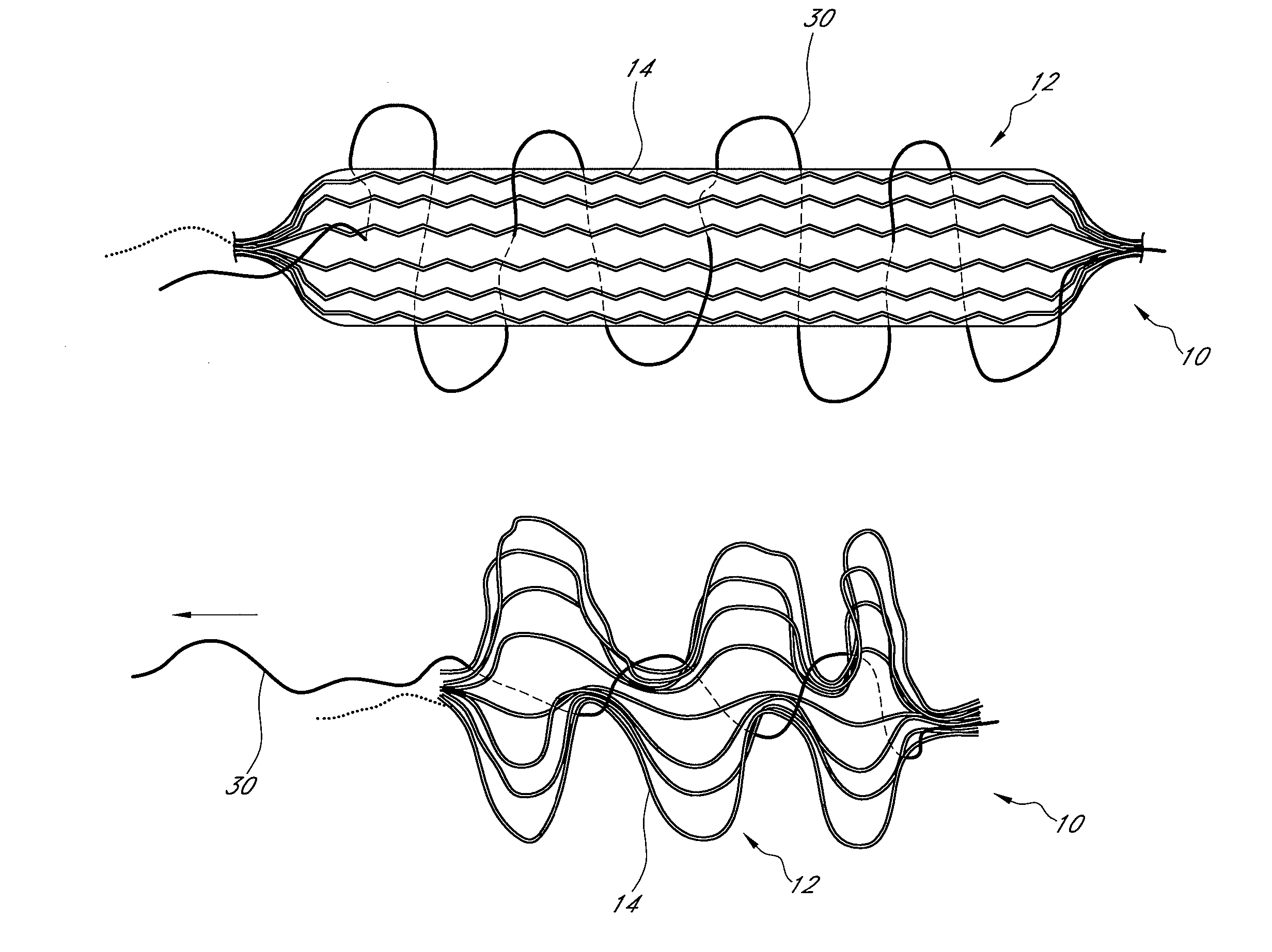
[0031] According to another embodiment, a method of treating a hollow anatomical structure having a diameter of 4 mm or more comprises inserting into the hollow anatomical structure a catheter having a size of 8 French or less. A bioabsorbable fibrous implant is passed through the catheter and into the hollow anatomical structure. With the implant, the patency of the hollow anatomical structure is reduced. According to some variations, the method further comprises occluding the hollow anatomical structure with the implant. The implant can be expanded to a treatment state within the hollow anatomical structure in some methods. The method can included promoting occlusive ingrowth with the implant when the implant is in the hollow anatomical structure. The hollow anatomical structure can comprise a vein. In some embodiments, the hollow anatomical structure comprises a greater saphenous vein. Inserting the catheter can comprise inserting the catheter at an insertion site spaced from the sapheno-femoral junction, and further comprise advancing the implant from the insertion site to the sapheno-femoral junction. The hollow anatomical structure can have a diameter of 4-12 mm in some embodiments. In some embodiments, the hollow anatomical structure can have a diameter of 4-20 mm.
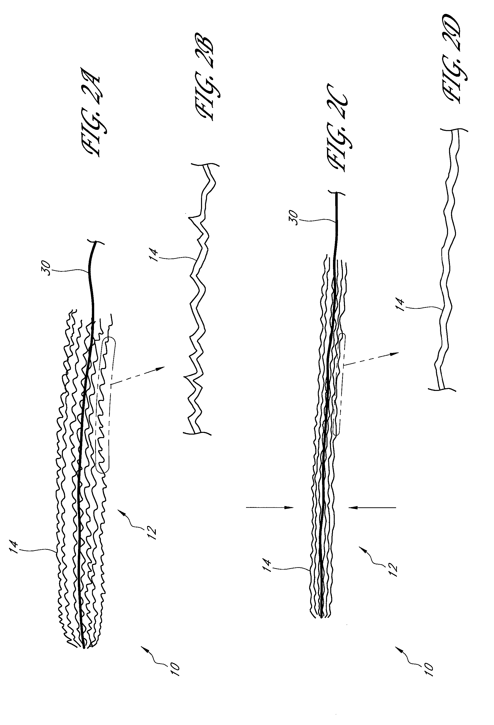
[0033] According to another embodiment, a method of treating a hollow anatomical structure comprises delivering into the hollow anatomical structure an implant comprising a plurality of loose tortuous fibers. The fibers are formed from one or more bioabsorbable materials. According to some variations, the method additionally comprises securing the implant in the hollow anatomical structure to limit migration of the implant within the hollow anatomical structure.

Problems solved by technology

When an incompetent valve is in the flow path, the valve is unable to close because the cusps do not form a proper seal and retrograde flow of the blood cannot be stopped.
When a venous valve fails, increased strain and pressure occur within the lower venous sections and overlying tissues, sometimes leading to additional, distal valvular failure.
The resulting condition is progressive and includes: dilation and tortuosity of the superficial veins of the lower limbs, unsightly discoloration, pain, swelling, and possibly ulceration.
This failure can also worsen deep venous reflux and perforator reflux.
Vein stripping is generally painful and requires a long recovery time.
This procedure is less favored and outcomes can be poor.
Procedures combining ligation and stripping are sometimes performed, but studies have shown they offer little advantage over stripping alone.
However it is not generally employed in the superficial venous system in humans.
Though not required for effective ligation, the vein wall can completely collapse, thereby resulting in a full-lumen obstruction that blocks the flow of blood through the vein.

Method used


Image

  • Expandable occlusive structure
  • Expandable occlusive structure
  • Expandable occlusive structure

Examples


Embodiment Construction

[0097] The following description and examples illustrate preferred embodiments of the present invention in detail. Those of skill in the art will recognize that there are numerous variations and modifications of this invention that are encompassed by its scope. Accordingly, the description of a preferred embodiment should not be deemed to limit the scope of the present invention.

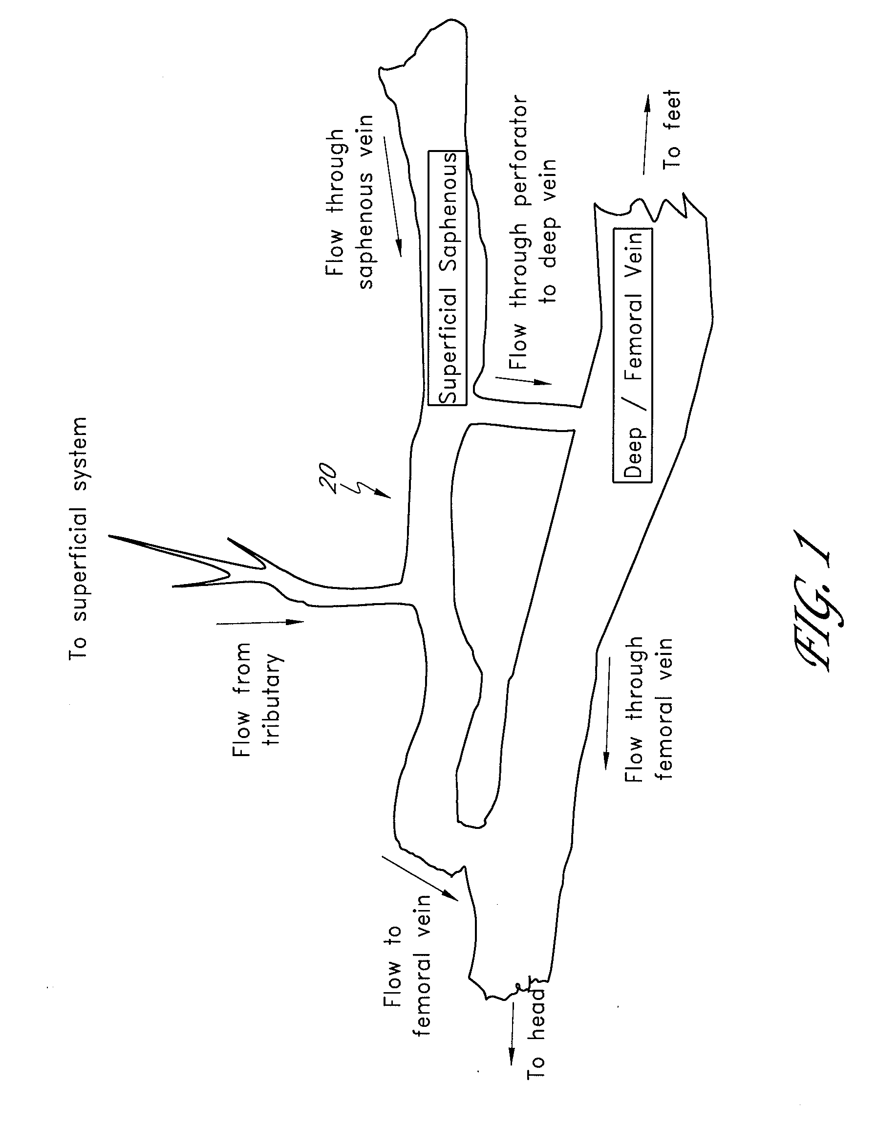
[0098] Methods, systems, and apparatuses for occluding a hollow anatomical structure (e.g., FIG. 1) in a patient or subject using an occluding device or occluding material are provided. The terms “subject” and “patient” as used herein, refer to animals, such as mammals. For example, mammals contemplated by one skilled in the art include humans, primates, dogs, cats, sheep, cattle, goats, pigs, horses, mice, rats, rabbits, guinea pigs, and the like. The terms “subject” and “patient” are used interchangeably.

[0099] The terms “occluding device” and “occluding material” as used herein, are broad terms and are ...


PUM


Abstract

An apparatus for treating a hollow anatomical structure comprises an implant comprising a plurality of bioabsorbable fibers. The implant has a compressed state in which the implant can fit within a cylindrical tube having an inside diameter of 8 French or less. The implant is expandable from the compressed state to an expanded state in which the implant has sufficient size to span the inside diameter of a cylindrical tube having an inside diameter of 12 French or greater.

Description

RELATED APPLICATIONS; PRIORITY [0001] This application claims the benefit under 35 U.S.C. § 119(e) of each of the following U.S. Provisional Patent Applications: No. 60 / 647,173, filed Jan. 25, 2005, titled STRUCTURES FOR PERMANENT OCCLUSION OF A HOLLOW ANATOMICAL STRUCTURE; No. 60 / 696,165, filed Jul. 1, 2005, titled STRUCTURES FOR PERMANENT OCCLUSION OF A HOLLOW ANATOMICAL STRUCTURE. The entirety of each of the above-mentioned provisional patent applications is hereby incorporated by reference herein and made a part of this specification.BACKGROUND OF THE INVENTION [0002] 1. Field of the Invention [0003] This invention relates to occlusion of a hollow anatomical structure by inserting an occluding device or occluding material into a hollow anatomical structure or surrounding native tissue. [0004] 2. Description of the Related Art [0005] The preferred embodiments relate generally to a method and material composition for introduction into a hollow anatomical structure (HAS) with parti...

Claims


Application Information

Patent Timeline
IPC IPC(8): A61F2/01
CPCA61B17/06A61B2017/1205A61B17/12031A61B17/12036A61B17/1204A61B17/12109A61B17/12136A61B17/12159A61B17/12172A61B17/12181A61B17/12186A61B17/1219A61B17/122A61B2017/00898A61B2017/0474A61B2017/06176A61B17/12022
Inventor KARABEY, HALIL I.PRESTEZOG, ANNA G.MIRIZZI, MICHAEL S.
Owner TYCO HEALTHCARE GRP LP
Learn More