Concurrent modeling technique for a part and its tooling

a technology of concomitant modeling and parts, applied in the field of automotive components and its tooling, can solve the problems of limited manufacturing tooling capabilities of mechanical parts, difficulty in initial design, manufacturing and tooling of parts, and difficulty in performing the actions associated with machining, handling and assembling of parts

Active Publication Date: 2006-09-21
FCA US
View PDF10 Cites 8 Cited by
  • Summary
  • Abstract
  • Description
  • Claims
  • Application Information

AI Technical Summary

Benefits of technology

[0004] A tooling and part design method comprises selecting a mechanical component. Data that is indicative of the mechanical component is determined. The data is modified in order to alter one or more dimensions

Problems solved by technology

Manufacturing tooling capabilities for mechanical parts may be limited due to the complexity of the parts.
Spatial limitations can cause difficulty during initial design, manufacturing, and tooling of the parts.
In particular, it can be difficult to perform actions associated with machining,

Method used


Image

  • Concurrent modeling technique for a part and its tooling
  • Concurrent modeling technique for a part and its tooling
  • Concurrent modeling technique for a part and its tooling

Examples


Embodiment Construction

[0012] The following description of the preferred embodiments is merely exemplary in nature and is in no way intended to limit the invention, its application, or uses.

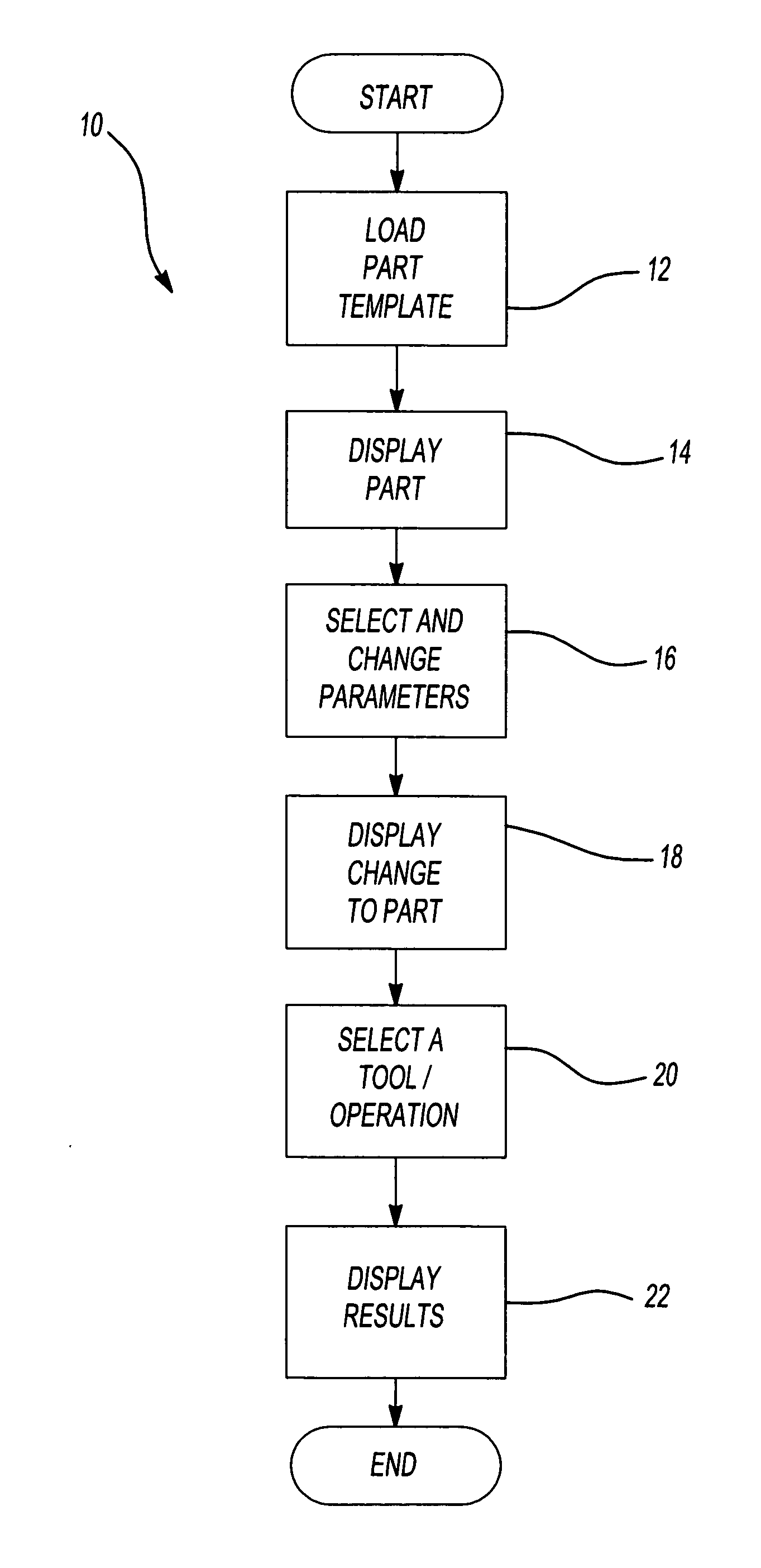
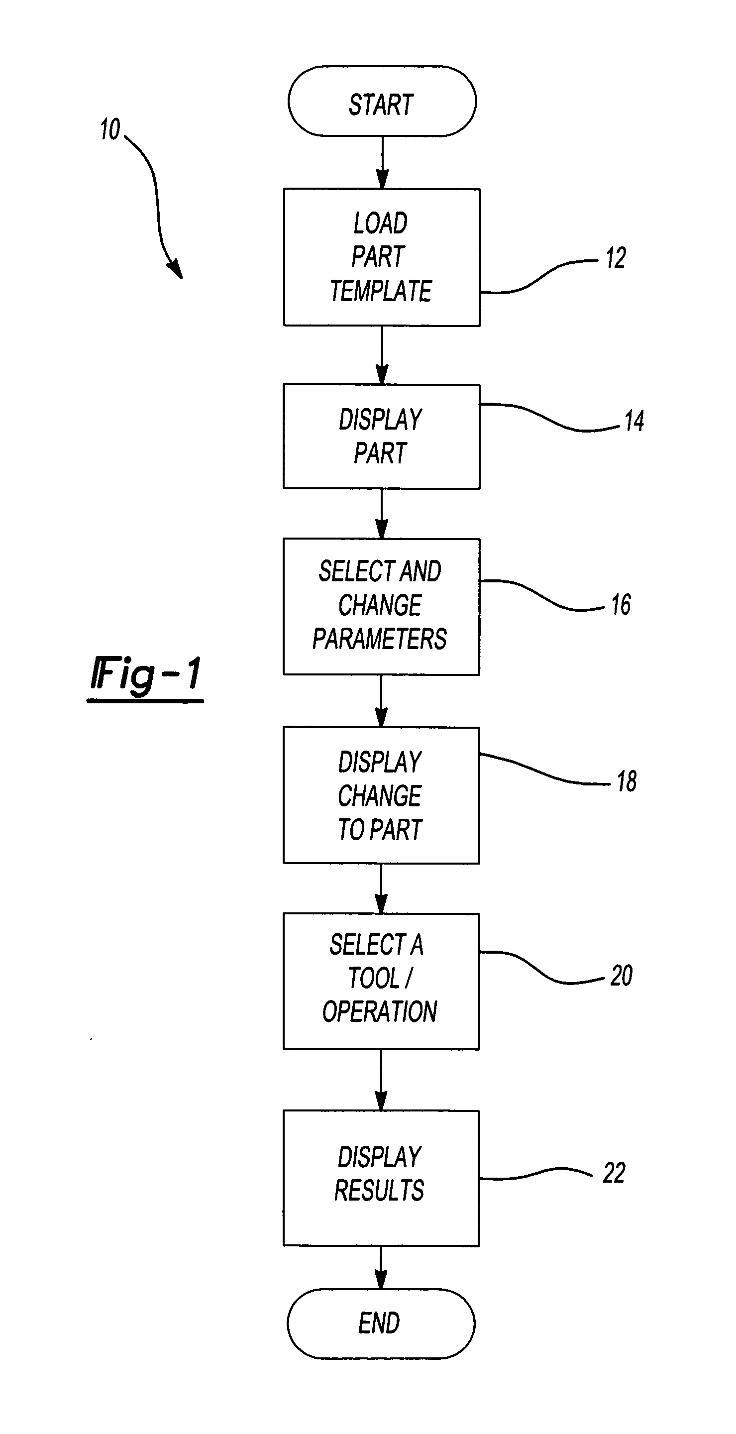
[0013] An automated tool and part modeling algorithm 10 is shown in FIG. 1. At step 12, a user selects a part and the algorithm 10 loads the part template. In the preferred embodiment, the user selects the part at a graphical user interface. The part template may include any suitable reference information indicating the dimensions of the part. For example, the part template may include, but is not limited to, parametric tooling data and the geometry of the tool and / or part. The part is displayed three-dimensionally to the user at the graphical user interface at step 14. At step 16, the user selects and changes a parameter in order to modify a particular feature or dimension of the part. For example, the user may change a location of a fastener, such as a bolt. The graphical user interface redisplays the part, reflecti...


PUM


Abstract

A tooling and part design method automatically detects tooling and machining interferences with a desired part design. A user selects a mechanical component. Data indicative of the mechanical component, such as a part template, is determined and displayed to the user. The user selects one or more design parameters of the mechanical component to modify. Any necessary tooling and/or machining functions are embedded in the data, and performed automatically on the mechanical component when the user modifies a design parameter. Any interferences caused by the modification are automatically identified to the user.

Description

FIELD OF THE INVENTION [0001] The present invention relates to tooling automotive components, and more particularly to concurrently modeling automotive components and the tooling thereof. BACKGROUND OF THE INVENTION [0002] Manufacturing tooling capabilities for mechanical parts may be limited due to the complexity of the parts. This is especially true in automotive applications. Spatial limitations can cause difficulty during initial design, manufacturing, and tooling of the parts. [0003] In particular, it can be difficult to perform actions associated with machining, handling, and assembling of the part due to interferences between the part and the particular tool being used. For example, although it may visually appear that an appropriate tool can be used at a particular location on a part, actual performance may result in permanent damage to the part. SUMMARY OF THE INVENTION [0004] A tooling and part design method comprises selecting a mechanical component. Data that is indicati...

Claims


Application Information

Patent Timeline
IPC IPC(8): G06F19/00
CPCG05B19/4069Y02P90/02
Inventor BRISEBOIS, PHILIPPE
Owner FCA US
Why Eureka
Try Eureka