
Floor covering material and method for manufacturing same

a technology for floor coverings and manufacturing methods, applied in the field can solve problems such as interrupting the usual monotonous appearance of floor covering materials, and achieve the effect of smooth production

Active Publication Date: 2021-06-15
FLOORING IND LTD
View PDF20 Cites 0 Cited by
  • Summary
  • Abstract
  • Description
  • Claims
  • Application Information

AI Technical Summary

Benefits of technology

The patent describes a floor covering material that is designed to look more life-like. The material has oblong elements that have lowered edges, which are formed by long edges. Instead of a lowered edge region with another geometry, no lowered edge region is present at the short edges. This feature helps to enhance the realism of the floor covering material. The floor covering material also has different depths between the lowered edge regions, which avoids an unnatural clean geometrical pattern. The lowered edge regions can be interrupted at the transverse panel edges to mask any possible running out of the lowered edge region. The covering material has a width between 2 and 6 meters and a length of several dozens of meters. The invention also includes a printed decor that is applied to the floor covering material using a printed foil or by printing directly onto the floor covering material. The printed decor is protected by a transparent wear layer. The invention provides a floor covering material that looks more life-like and is easier to produce.

Problems solved by technology

The presence of lowered edge regions as such already interrupts the usual monotonous appearance of the floor covering material.

Method used


Image

  • Floor covering material and method for manufacturing same
  • Floor covering material and method for manufacturing same
  • Floor covering material and method for manufacturing same

Examples


Embodiment Construction

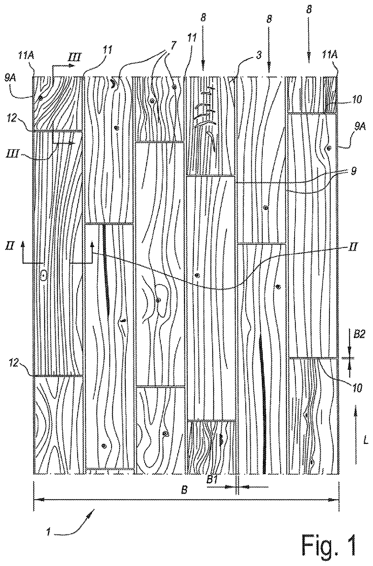
[0060]FIG. 1 represents a portion of a floor covering material 1. In this case, this relates to a web-shaped floor covering material 1. The width B of such floor covering material 1 can vary between 2 and 6 meters and preferably is from 3.5 to 5.5 meters. The length L can be various dozens of meters, for example, between 20 and 50 meters. In the example, this relates to a floor covering material 1 which is supplied from a roll.

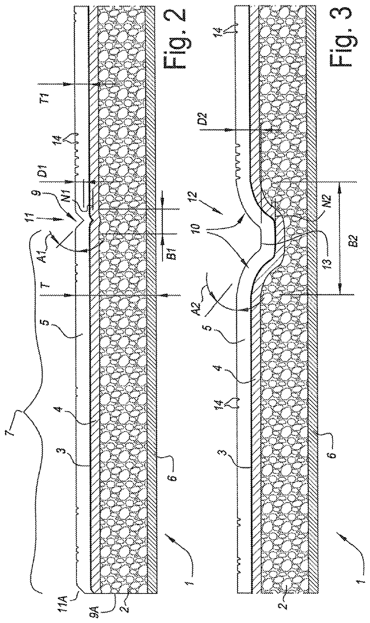
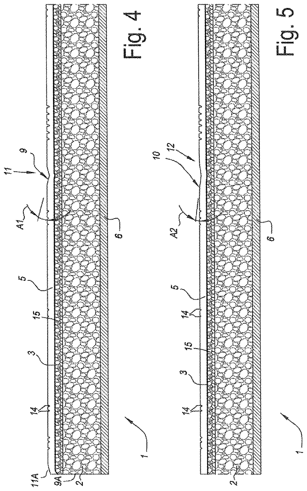
[0061]FIG. 2 clearly shows that this floor covering material 1 comprises at least a foamed layer 2 and a printed decor 3 provided thereon. The foamed layer 2 relates to a foamed PVC layer, or so-called “cushion vinyl”. In this case, the printed decor 3 is provided as a printed PVC foil 4 having, for example, a thickness of 60 micrometers to 150 micrometers. In this case, a transparent wear layer 5 is provided above the printed decor 3. The wear layer 5 preferably has a thickness T1 of 0.15 to 0.75 millimeters, and still better between 0.25 and 0.55 millimeters...


PUM

PropertyMeasurementUnit
transparentaaaaaaaaaa

Abstract

Floor covering material, wherein this floor covering material comprises at least a foamed layer, a printed decor provided thereon, and preferably a transparent wear layer, wherein the printed decor represents a plurality of panel-shaped or tile-shaped elements, wherein at the edges of said represented elements, lowered edge regions are formed, which form at least a portion of the circumference of the respective element, wherein said lowered edge regions, seen in cross-section, are realized with at least two different geometries. The invention further also relates to a method for manufacturing such floor covering material.

Description

BACKGROUND OF THE INVENTION[0001]This invention relates to a floor covering material and a method for manufacturing the same.[0002]More particularly, the invention relates to a floor covering material of the so-called “cushion vinyl” type. Such floor covering material is widely known, for example, from CA 1 046 869 and WO 2005 / 118947. Herein, this may relate to a web-shaped floor covering material which is supplied from a roll. Then, in a room a plurality of webs cut to length can be installed next to each other, for example, by gluing the respective webs at their edges onto the subfloor or onto the underlying floor. Floor covering material of the “cushion vinyl” type can be composed starting with a carrier (In English, also called a “liner”), on which a foamed layer is situated, namely, the actual cushion vinyl layer. This foamed layer as such can consist of one or more sublayers. On the foamed layer then a printed decor is situated. The printed decor either can be applied as a foi...

Claims


Application Information

Patent Timeline
Patent Type & Authority Patents(United States)
IPC IPC(8): E04F15/02B32B38/00B32B38/06B44C1/24E04F15/10B44C5/04D06N7/00B32B37/24E04F13/08
CPCE04F15/02038B32B37/24B32B38/06B32B38/145B44C1/24B44C5/04D06N7/0007D06N7/0013E04F15/02033E04F15/02161E04F15/105E04F15/107B32B2038/0084B32B2255/08B32B2255/28B32B2307/554E04F13/0866E04F13/0873E04F13/0894E04F2201/0115E04F2203/02
Inventor DUYCK, STEFAAN GERARD LUCIENVAN VLASSENRODE, KRISTOF
Owner FLOORING IND LTD
Learn More