Radio frequency identification application system

a technology of radio frequency identification and application system, which is applied in the direction of burglar alarm mechanical actuation, electromagnetic radiation sensing, instruments, etc., can solve the problems of inconvenient no single standard enjoys universal acceptance, and requirements of this type are disruptive to suppliers' operations, systems, personnel, costs and schedules, etc., to facilitate proper placement of rfid tags

Active Publication Date: 2006-09-21
SML INTELLIGENT INVENTORY SOLUTIONS
View PDF6 Cites 65 Cited by
  • Summary
  • Abstract
  • Description
  • Claims
  • Application Information

AI Technical Summary

Benefits of technology

[0015] These and other problems are generally solved or circumvented, and technical advantages are generally achieved, by advantageous embodiments of the present invention that include a radio frequency identification (“RFID”) application system for use with an RFID system adapted to apply an RFID tag to a product and method of operating the same. In one embodiment, the RFID application system includes a printer applicator controller config

Problems solved by technology

Present systems are unable to satisfy the mandates, in general, and if the systems approach satisfying such mandates, the cost thereof is prohibitive.
In addition, no single standard enjoys universal acceptance, so multiple standards are being adopted.
Requirements of this type are disruptive to suppliers' operations, systems, personnel, costs and schedules.
In addition, RFID mandates have imposed constraints on the suppliers and the constraints have generated additional problems as described below.
Attempts to respond to the basic changes in the supply chain management have not been successful.
Suppliers have implemented various manual processes to meet the compliance requirements, which have proven to be costly, inefficient, and prone to errors that are difficult to detect and correct.
Compounding the problem is the fact that future requirements will be more extensive (more RFID-enabled distribution centers, SKUs and suppliers) than those now in place and these will only further aggravate the problem.
In light thereof, existing solutions concentrate on more hardware and labor to address the problem, which only ramps up the amount of losses incurred to implement the processes and further aggravates the issues of error checking, error detection and error correction.
Additionally, expanding the manual approaches is not efficiently scalable or tenable.
While the manual process allows businesses to scale, it is labor and hardware intensive and leads to a proportional increase in errors associated with the application of the RFID tags on products and the like.
While the m

Method used


Image

  • Radio frequency identification application system
  • Radio frequency identification application system
  • Radio frequency identification application system

Examples


Embodiment Construction

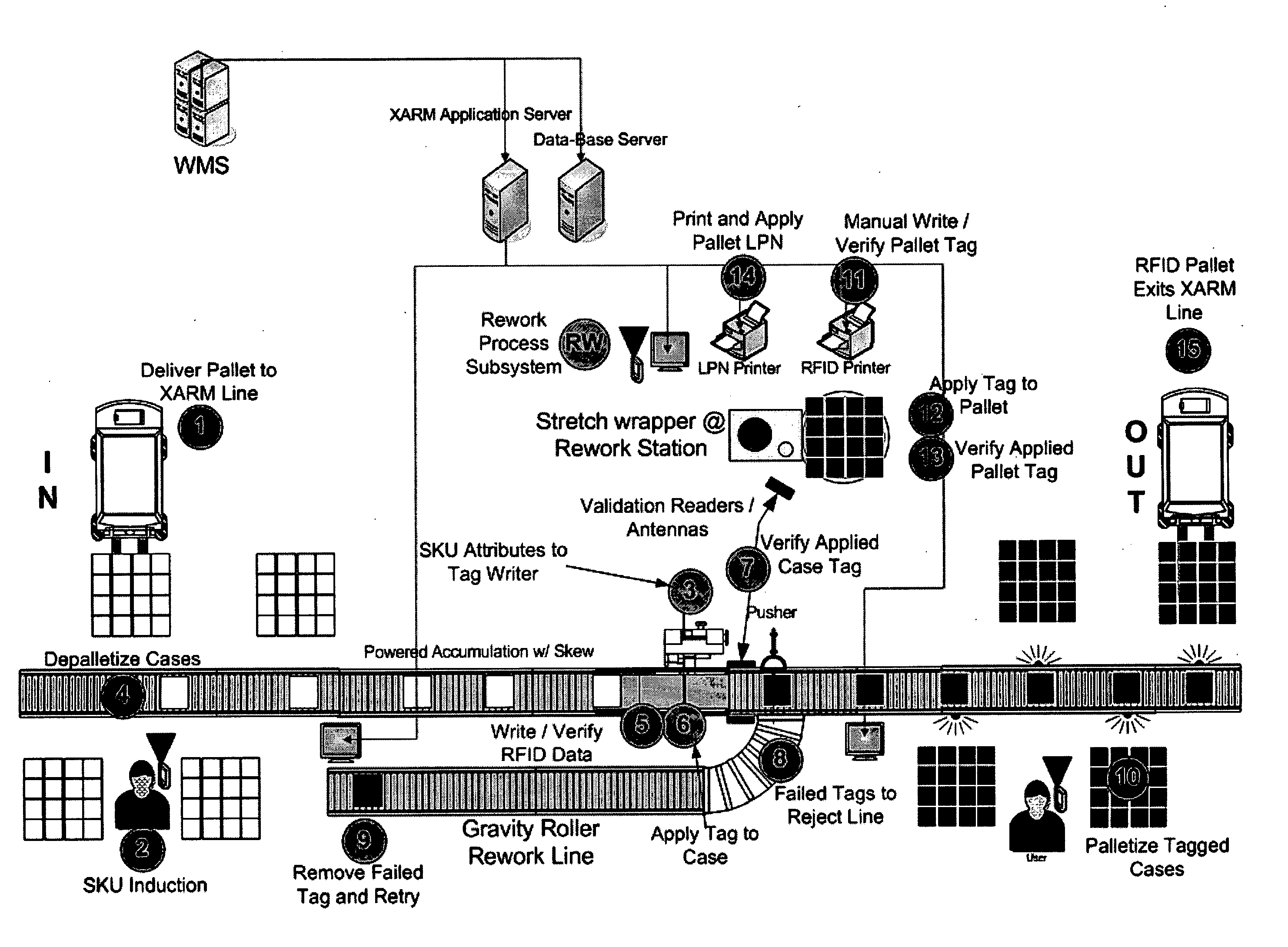
[0023] The making and using of the presently preferred embodiments are discussed in detail below. It should be appreciated, however, that the present invention provides many applicable inventive concepts that can be embodied in a wide variety of specific contexts. The specific embodiments discussed are merely illustrative of specific ways to make and use the invention, and do not limit the scope of the invention. Unless otherwise provided, like designators for devices employed in different embodiments illustrated and described herein do not necessarily mean that the similarly designated devices are constructed in the same manner or operate in the same way.

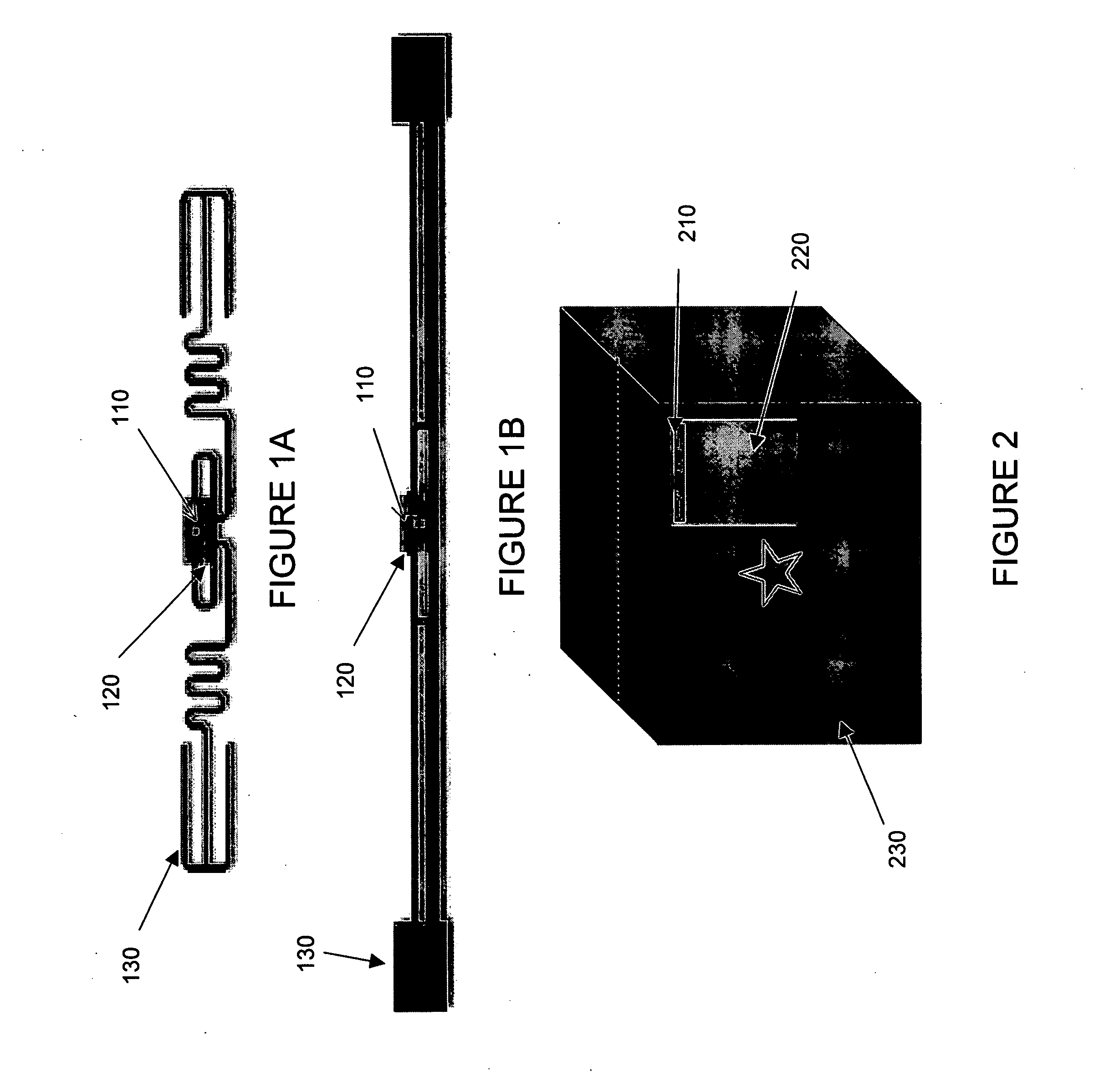
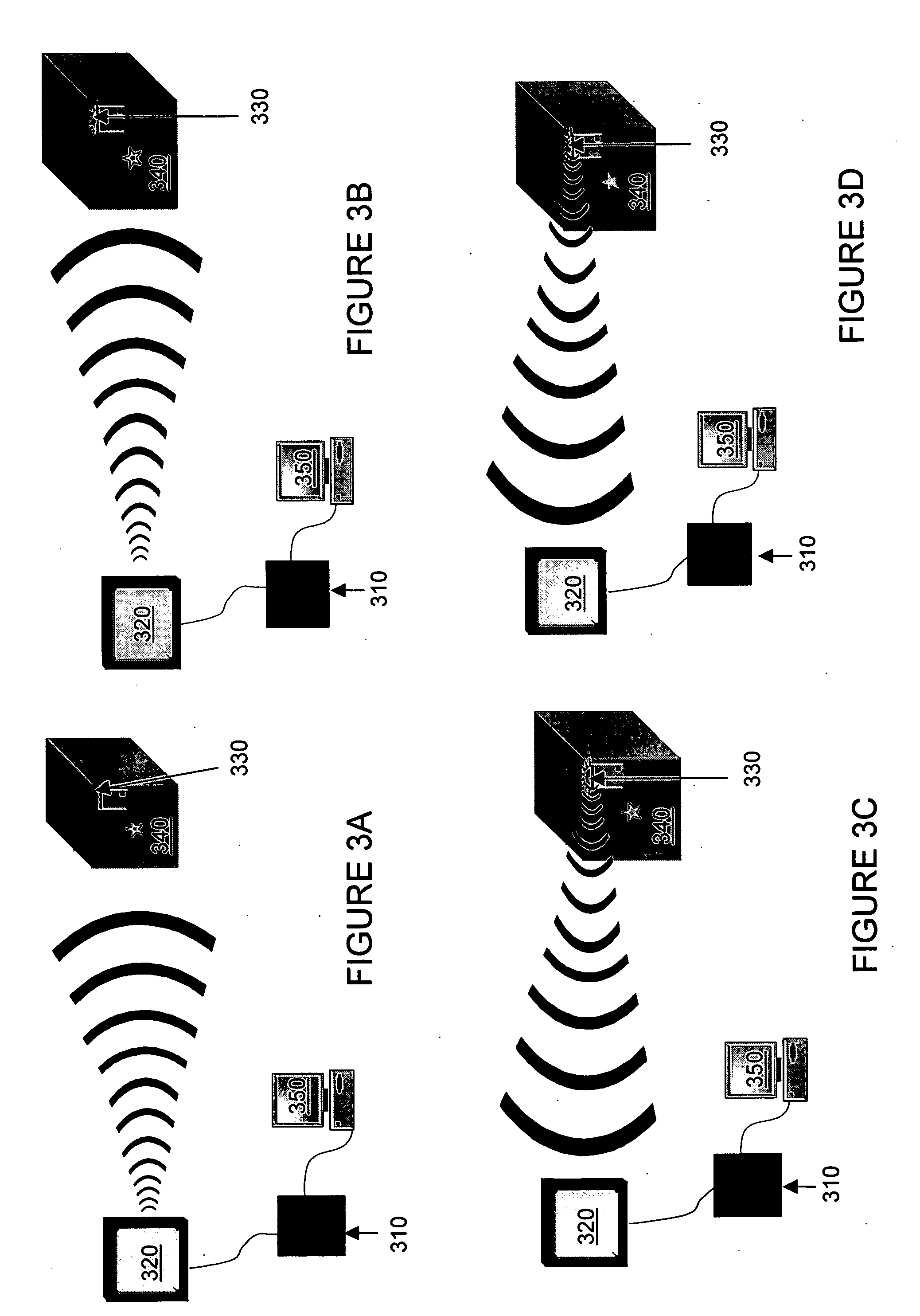
[0024] The present invention will be described with respect to an exemplary embodiment in a specific context, namely, an RFID application system within an RFID system. The particular embodiments described herein are applied supply chain management systems in the retail industry. The principles of the present invention may be appli...


PUM


Abstract

A radio frequency identification (“RFID”) application system for use with an RFID system adapted to apply an RFID tag to a product and method of operating the same. In one embodiment, the RFID application system includes a printer applicator controller configured to manage an operation of a printer applicator of the RFID system. The RFID application system also includes a compliance manager configured to coordinate RFID compliance data to derive a unique identification number for the RFID tag. The RFID application system still further includes an event manager configured to coordinate an operation of the printer applicator controller to facilitate proper placement of the RFID tag on the product.

Description

[0001] This application claims the benefit of U.S. Provisional Application No. 60 / 657,023, entitled “Automated RFID Supply Chain Management System,” filed on Feb. 28, 2005, which is incorporated herein by reference. Technical Field [0002] The present invention is directed, in general, to radio frequency identification (“RFID”) systems and, in particular, to an RFID application system and method of operating the same. Background [0003] Radio frequency identification (“RFID”) systems include RFID readers communicating with RFID tags via radio waves. The RFID readers send radio signals via antennas, which are received by the RFID tags. The RFID tags may be passive, semi-active or active. The passive RFID tags are the most common and least costly and derive energy for operation from the transmitted signal from the RFID reader thereby illuminating the RFID tag. The semi-active and active RFID tags have independent power sources for processing functions and for independent or enhanced tra...

Claims


Application Information

Patent Timeline
IPC IPC(8): G06F7/00G06F17/00G08B13/14
CPCG06K17/00G06K17/0025
Inventor ABRAHAM, THOMAS C. JR.AHEARN, DANIEL J.BHUMIREDDY, CHANDRAKUMARFREW, DEAN L.VELUPULA, BALARAJUWILSON, MATTHEW D.
Owner SML INTELLIGENT INVENTORY SOLUTIONS
Why Eureka
Try Eureka