Automatic bridge balancing means and method for a capillary bridge viscometer

a bridge and viscometer technology, applied in the direction of instruments, ac/dc measuring bridges, fluid pressure measurement, etc., can solve the problems of inefficient delay of fluid sample testing, original tuning to slowly drift with time, and general tediousness and time consumption, and achieve the widest operating range and accurate measurement signals.

Active Publication Date: 2006-09-28
WYATT TECH
View PDF12 Cites 8 Cited by
  • Summary
  • Abstract
  • Description
  • Claims
  • Application Information

AI Technical Summary

Benefits of technology

[0008] Instead of varying the length of one fluid arm of a capillary bridge viscometer as has been accomplished in the past, an independently controlled thermal stage is connected within at least one arm of the bridge to achieve the desired balance. The thermal stage includes a tuning capillary tubing portion that is wrapped around a thermally conductive (e.g., brass or copper) core. The core and the tuning capillary tubing portion wrapped therearound are isolated from the other fluid arms of the bridge within an insulated thermal housing.
[0009] A (e.g. resistance) heater or a Peltier thermoelectric device is located within the thermal housing to lie in close thermal contact with the tuning capillary tubing portion. A temperature probe is also located within the housing so as to be responsive to the temperature of the capillary tubing portion. With the bridge of the capillary bridge viscometer ini...

Problems solved by technology

This is generally tedious and time consuming.
Moreover, some fluid samples such as proteins, and the like, are known to stick to the fluid tubing which causes the original tu...

Method used


Image

  • Automatic bridge balancing means and method for a capillary bridge viscometer
  • Automatic bridge balancing means and method for a capillary bridge viscometer
  • Automatic bridge balancing means and method for a capillary bridge viscometer

Examples


Embodiment Construction

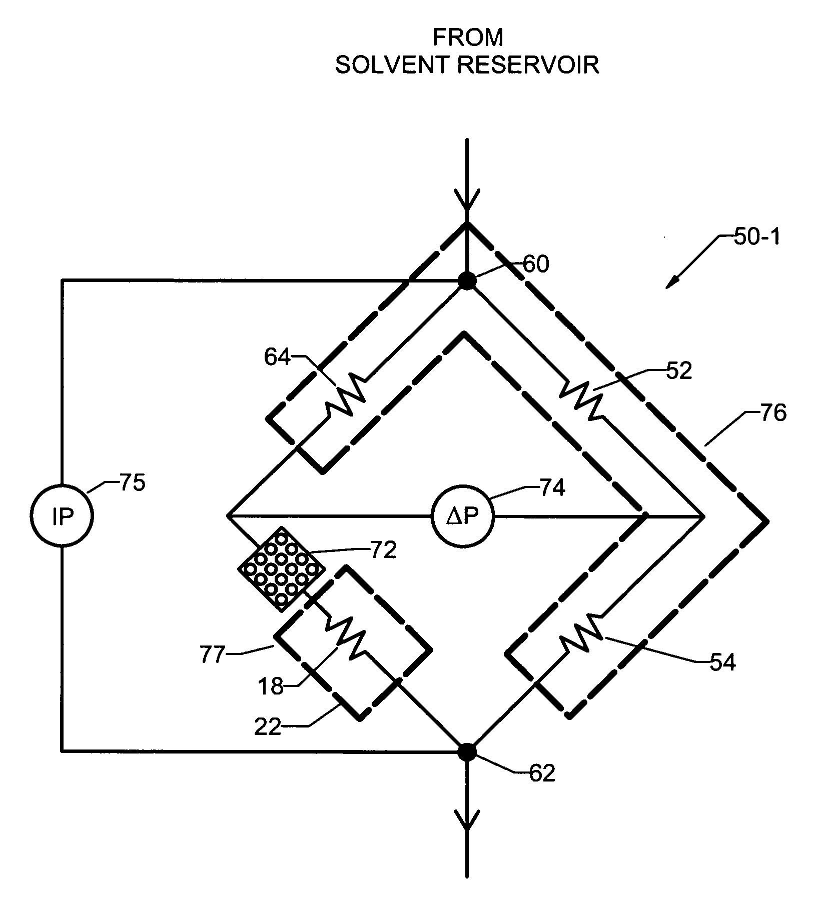
[0014] Disclosed herein is an automatic bridge balancing method and means for a capillary bridge viscometer. Viscosity is known to be a strong function of temperature. Therefore, it is contemplated to control the temperature of the fluid arms of the bridge viscometer to insure that the only pressure differences measured are due to changes in the composition of the sample rather than to thermally induced variations of the viscosity. The present improvement relies on using this strong temperature dependence as a tuning method.

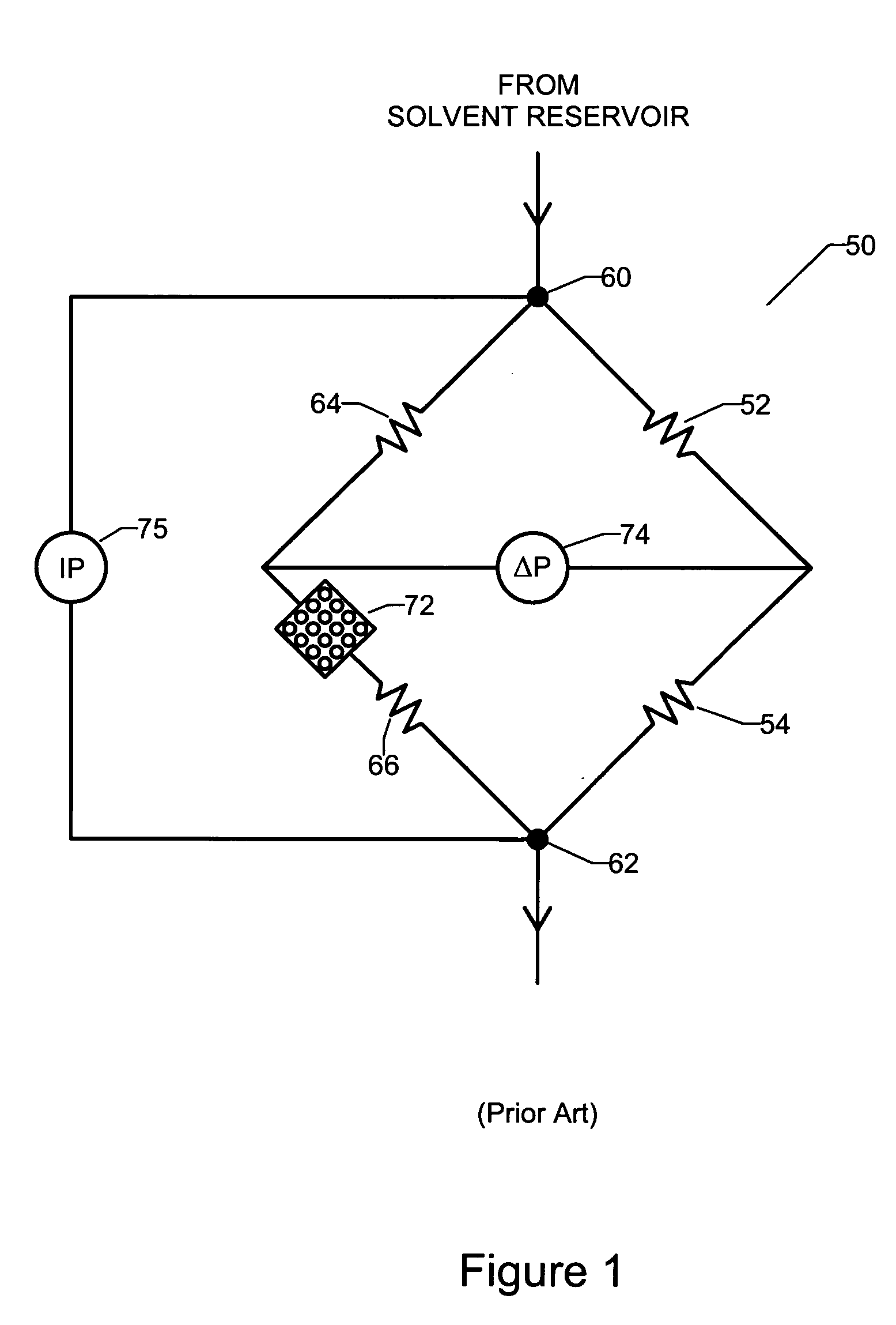
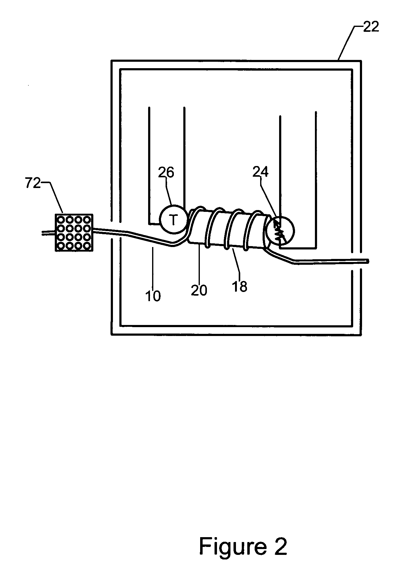
[0015] Rather than attempting to mechanically tune the bridge 50 of FIG. 1 while encountering the inconvenience and time delay associated with changing the length of one fluid arm thereof to constantly keep the bridge in balance, it has been discovered that the bridge may be balanced by heating or cooling the arm. More particularly, instead of adjusting the length of a fluid tubing line to tune the bridge, it has been found that a more efficient approach is to h...


PUM


Abstract

A thermally controlled stage is connected within one arm of a bridge of a capillary bridge viscometer so that the bridge can be balanced in situ to provide accurate measurement signals. The thermally controlled stage includes a tuning capillary tubing portion that is wrapped around a thermally conductive core. A resistance heater or a Peltier thermoelectric device is located in close proximity to the capillary tubing portion. The heater or Peltier device and the capillary tubing portion are located within a thermally insulated housing. The heater or Peltier device varies the temperature of the capillary tubing portion to cause a corresponding change in the flow impedance of the tuning capillary tubing portion of the arm of the bridge in which the thermally controlled stage is connected. The temperature of the tuning capillary tubing portion is monitored and adjusted until any pressure differential across the bridge is eliminated, whereby to trim in the balance of the bridge.

Description

BACKGROUND OF THE INVENTION [0001] 1. Field of the Invention [0002] This invention relates to a bridge balancing method and to a thermally controlled stage that is connected within one arm of a capillary bridge viscometer so that the temperature of the one arm can be controlled to a different temperature than the temperatures of the other three arms. This allows the bridge be automatically balanced to provide accurate measurement signals. [0003] 2. Background Art [0004] An example of a capillary bridge viscometer which is adapted to accurately measure the specific viscosity of a solute in a suitable solvent is available by referring to U.S. Pat. No. 4,463,598 issued Aug. 7, 1984. Such a capillary bridge viscometer is useful in determining the molecular parameters of a polymer including molar mass and hydrodynamic radius. FIG. 1 of the drawings illustrates this well known capillary bridge viscometer. [0005] The aforementioned patented differential viscometer includes a capillary brid...

Claims


Application Information

Patent Timeline
IPC IPC(8): G01N11/08
CPCG01N11/08G01N2011/002
Inventor TRAINOFF, STEVEN P.
Owner WYATT TECH
Why Eureka
Try Eureka