
Telescoping jack unit

a telescopic jack and jack technology, applied in the direction of vehicle fittings for lifting, vehicle maintenance, transportation and packaging, etc., can solve the problems of requiring a significant number of revolutions to raise or lower the trailer jack, cumbersome use of swivel jacks, and damage to jacks, so as to achieve rapid and efficient transition, cost-effective

Inactive Publication Date: 2006-09-28
NETWORK APPLIANCE INC
View PDF5 Cites 12 Cited by
  • Summary
  • Abstract
  • Description
  • Claims
  • Application Information

AI Technical Summary

Benefits of technology

[0015] It is another object of the present invention to provide a telescoping jack device that may quickly and easily be manipulated between its stowed and ground-engaged position.
[0016] It is another object of the present invention to provide a telescoping jack device that may remain in its stowed position during transport.
[0017] It is another object of the present invention to provide a telescoping jack device that is simple to manufacture.
[0018] It is another object of the present invention to provide a telescoping jack device that is affordable.
[0019] In satisfaction of these and other related objectives, the present invention provides a device for raising and lowering a trailer. The present invention provides a device, which may remain attached to a trailer at all times. As will be discussed in the specification to follow, practice of the present invention allows for quickly and efficiently manipulating the device from its elevated, stowed position to its ground-engaged position, ready for lifting the trailer.
[0022] In summary, then, an embodiment of the present invention provides a cost-effective jacking mechanism that can quickly and efficiently be transitioned from its elevated, stowed position to its lowered, ground-engaged position. Correspondingly, the mechanism can just as quickly be transitioned from its lowered, ground-engaged position to its elevated, stowed position, where it may be left attached to the trailer during transport without the fear of damage from ground obstructions.

Problems solved by technology

Traditional swivel jacks are cumbersome to use and have substantial drawbacks.
In fact, enough space must exist between the foot of the jack and the ground to be able to move and manipulate a trailer without the jack being in a position to contact an obstruction, which would damage the jack.
Thus, raising or lowering the trailer jack requires a significant number of revolutions, in turn, requiring a significant amount of time and effort each time the trailer is engaged or disengaged from a tow vehicle.
Therefore, the manually operated hydraulic jack suffers from the same substantial impediment as the swivel jack.
That is, the time and effort it takes to move the jack foot from its elevated, stowed position to its lowered, ground-engaged position is significant.
In contrast, motorized hydraulic jacks operate much more quickly, but they suffer from another drawback, which is the significantly increased cost and complexity of the motorizing device itself.

Method used


Image

  • Telescoping jack unit
  • Telescoping jack unit

Examples


Embodiment Construction

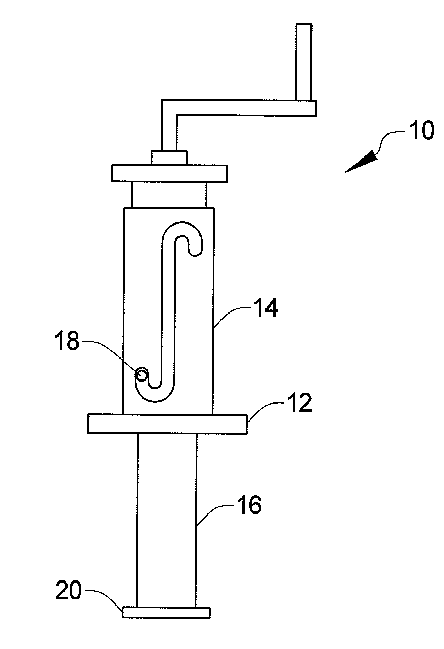
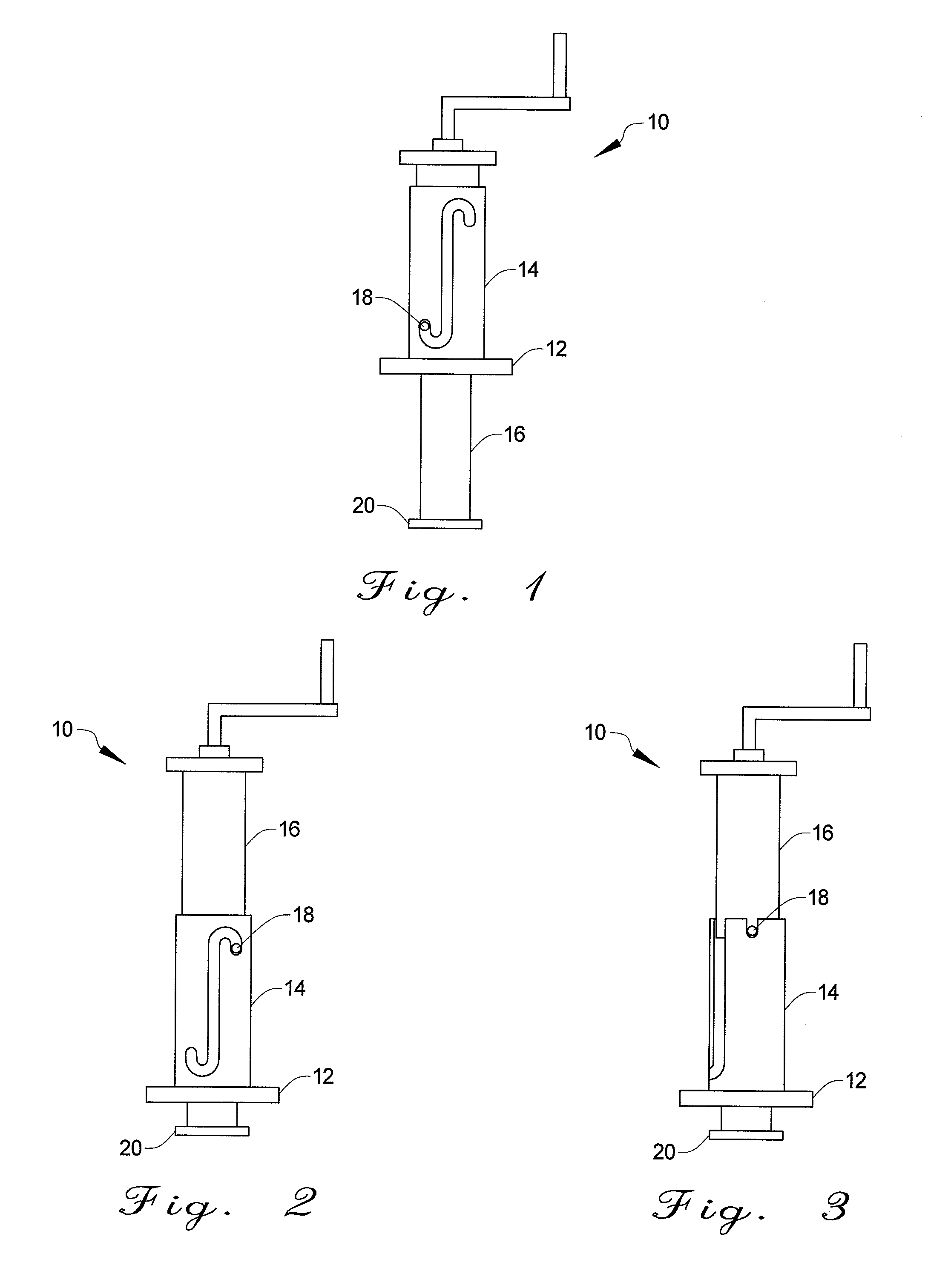
[0027] Referring to FIGS. 1, 2, and 3, a telescoping jack is shown and is generally designated by numeral 10. Referring principally to FIGS. 1 and 2, the preferred embodiment of the present invention is shown, in its most basic form, comprising mounting member (12), support member (14), and jack member (16). Mounting member (12) is configured to mount to a typical trailer coupling configuration and is rigidly attached to support member (14). In the preferred embodiment, mounting member (12) is configured of mild steel and welded to support member (14), which is also preferably a mild steel; however, other materials are envisioned with suitable, high strength characteristics, such as various ferrous and non-ferrous metals, thermoformed plastic materials, and injection molded thermoplastic materials. Accordingly, the attachment means between mounting member (12) and support member (14) should be a suitable strength connection, according to the materials used.

[0028] Referring back to ...


PUM


Abstract

The present invention is directed toward an apparatus for quickly configuring a jack to raise a load from its rest position. In particular, the present invention provides a jacking mechanism that telescopes from a locked, elevated position to a locked, lowered position in order to situate the jacking mechanism for raising a load. Correspondingly, the present invention provides a jacking mechanism that telescopes from its locked, lowered position to its locked, elevated position for stowing the mechanism between uses.

Description

CROSS-REFERENCE TO PRIOR APPLICATION [0001] This application is a continuation-in-part of U.S. patent application Ser. No. 10 / 965,363, filed Oct. 14, 2004.BACKGROUND OF THE INVENTION [0002] 1. Field of the Invention [0003] The present invention is directed toward an apparatus for quickly configuring a jack to raise a load from its rest position. In particular, the present invention provides a jacking mechanism that telescopes from a locked, elevated position to a locked, lowered position in order to situate the jacking mechanism for raising a load. Correspondingly, the present invention provides a jacking mechanism that telescopes from its locked, lowered position to its locked, elevated position for stowing the mechanism between uses. [0004] 2. Background Information [0005] The use of jacking mechanisms, specifically those used in combination with trailers, is well known in the art. Furthermore, jacks heretofore devised and utilized are known to consist of familiar, expected and ob...

Claims


Application Information

Patent Timeline
Patent Type & Authority Applications(United States)
IPC IPC(8): B60S9/02
CPCB60S9/08
Inventor MEISSNER, JASON ROBERT
Owner NETWORK APPLIANCE INC
Learn More