Method and apparatus for frequency modulating a periodic signal of varying duty cycle

a frequency modulation and duty cycle technology, applied in pulse generators, pulse techniques, instruments, etc., can solve problems such as the tendency of pwm to alter pulse width characteristics, and the interference of electronic system operation by applying spread spectrum techniques

Active Publication Date: 2008-07-03
SEMICON COMPONENTS IND LLC
View PDF4 Cites 43 Cited by
  • Summary
  • Abstract
  • Description
  • Claims
  • Application Information

AI Technical Summary

Benefits of technology

[0012]The present invention generally comprises a method and apparatus for frequency modulating a periodic signal of varying duty cycle. More specifically, the invention frequency modulates a PWM signal to spread the frequency of the PWM and reduce the magnitude of spectral components of the PWM.
[0013]One embodiment of the invention involves a method that includes the steps of: 1) generating a high frequency carrier signal much greater in frequency than the PWM signal; 2) modulating the high frequency signal by any one of the many known methods to generate a spread spectrum carrier signal; and, 3) retiming a PWM signal with this high frequency SS carrier signal. That is, the binary transitions of the PWM signal are thus aligned with the frequency varying carrier signal, causing the spectral components of the PWM signal to be diffused and reduced in magnitude. A significant outcome of this process is that the pulse width of the PWM signal is not altered in any significant way, on a per cycle basis, so that the PWM characteristics and information content are maintained. Thus, for example, a desired duty cycle may be preserved, even though the PWM signal is spread and EMI is attenuated.
[0019]In a second embodiment, the method described above is modified somewhat with the addition of an adaptive retiming arrangement. That is, the high frequency carrier signal (hereafter the clock signal) is modified so that it tracks the PWM duty cycle. The maximum value of the instantaneous clock period is no more than one-half the width of the narrowest PWM pulse or PWM gap between pulses. Thus the clock frequency is varied, with the frequency increasing significantly when the PWM duty cycle gets very low or very high. As before, the clock signal (the carrier signal) is also frequency modulated with a spread spectrum modulation profile. The higher frequency clock signal during very high / very low PWM duty cycles enables the system to resolve rapid binary transitions in the PWM signal and apply SS-induced EMI attenuation to the PWM signal.

Problems solved by technology

EMI (electromagnetic interference) is the generation of undesired radiation energy which has the potential of interfering with the operation of electronic systems.
It appears that attempts to apply spread spectrum techniques to PWM tend to alter the pulse width characteristics on a per cycle basis, due to the shifting frequency of the pulse signal.

Method used


Image

  • Method and apparatus for frequency modulating a periodic signal of varying duty cycle
  • Method and apparatus for frequency modulating a periodic signal of varying duty cycle
  • Method and apparatus for frequency modulating a periodic signal of varying duty cycle

Examples


Embodiment Construction

[0057]The present invention generally comprises a method and apparatus for frequency modulating a periodic signal of varying duty cycle to reduce the magnitude of spectral components of the periodic signal.

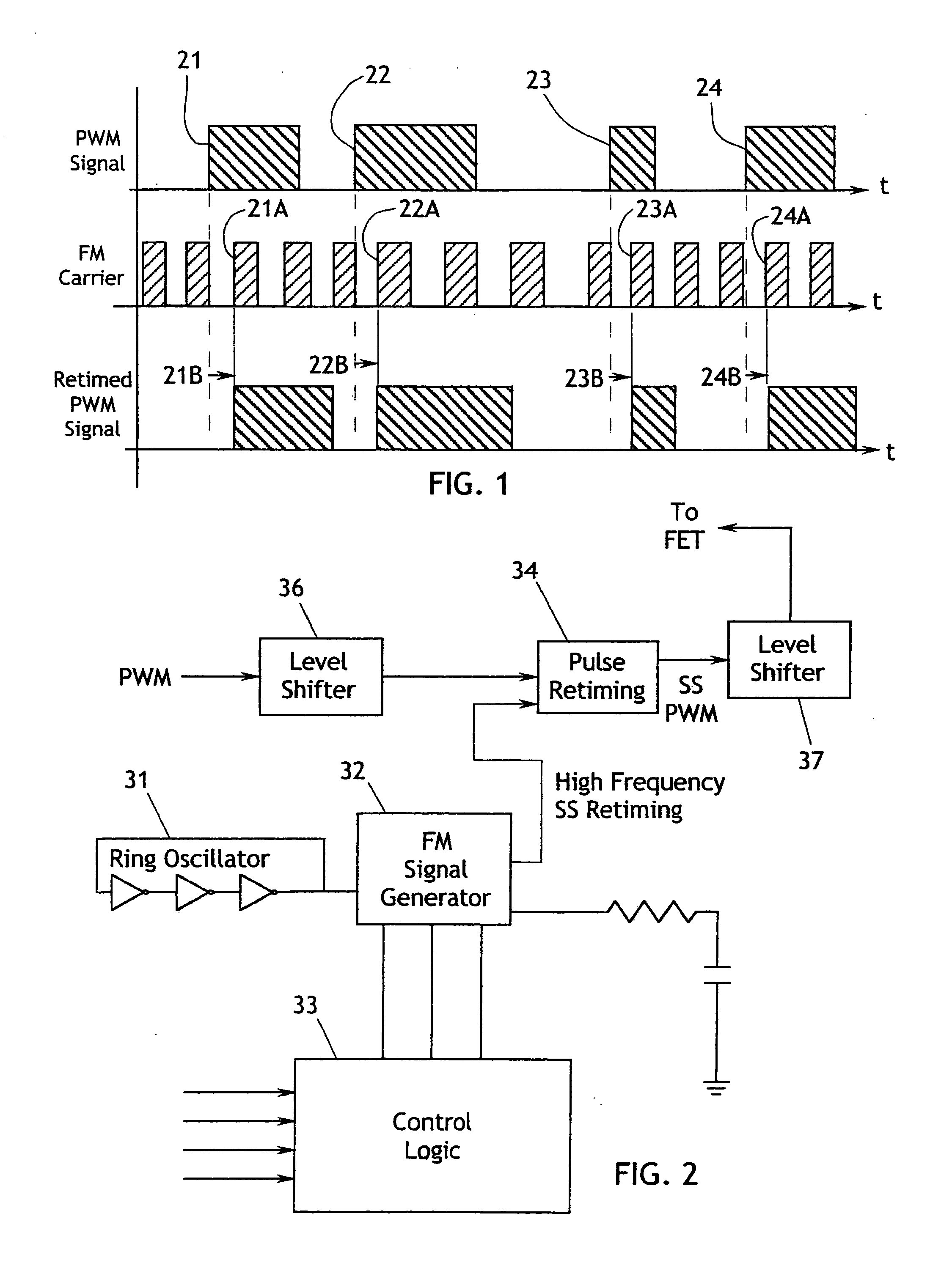
[0058]With regard to FIG. 1, one embodiment of the invention is a method including the steps of generating or acquiring a periodic signal, such as a PWM signal, as shown at the top of the figure. A PWM signal generally has a constant frequency and a variable duty cycle (pulse width). Thus the upward transition of each cycle occurs at a constant frequency, while the downward transition of each cycle depends on the pulse width of that cycle. The constant frequency of the upward transitions tends to cause a large, spike-like component in the EM spectrum of the PWM signal, a component that may comprise unacceptable electromagnetic interference.

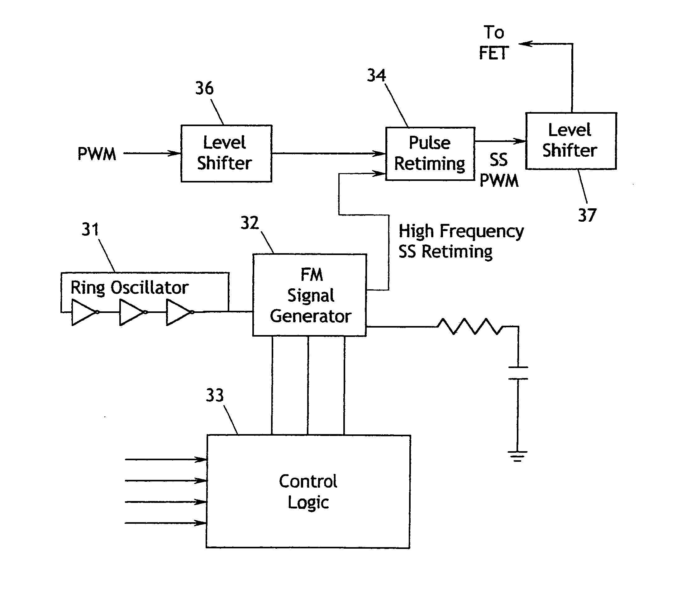
[0059]The method also includes generating a frequency modulated carrier signal. In FIG. 1, the FM signal is a square wave that may or may not h...


PUM


Abstract

A method and apparatus for frequency modulating a PWM involves 1) generating a high frequency carrier signal much greater in frequency than the PWM signal; 2) modulating the high frequency signal to generate a spread spectrum carrier signal; and, 3) retiming a PWM signal with this high frequency SS carrier signal so that the binary transitions of the PWM signal are aligned with the frequency varying carrier signal. In another embodiment, a PWM oscillator is driven by a second, FM oscillator having spread spectrum characteristics. In another embodiment a PWM oscillator is driven and modulated by a counter / frequency divider comprised of modules.

Description

CROSS-REFERENCE TO RELATED APPLICATIONS[0001]This application is a divisional application of patent application Ser. No. 11 / 115,550, filed Apr. 26, 2005, for which priority is claimed.FEDERALLY SPONSORED RESEARCH[0002]Not applicable.SEQUENCE LISTING, ETC ON CD[0003]Not applicable.BACKGROUND OF THE INVENTION[0004]1. Field of the Invention[0005]The present invention generally, relates to the reduction of EMI in systems using a Pulse Width Modulated (PWM) signal. A PWM signal is defined as a periodic signal in which the duty cycle or pulse width may vary from one cycle to another. PWM signals are used in numerous applications such as motor drive control, error sensing and power supply design.[0006]2. Description of Related Art[0007]EMI (electromagnetic interference) is the generation of undesired radiation energy which has the potential of interfering with the operation of electronic systems. Regulatory bodies exist in most countries to set standards and guidelines for EMI and these bo...

Claims


Application Information

Patent Timeline
Patent Type & Authority Applications(United States)
IPC IPC(8): H03K7/08
CPCH03K7/08H04B2215/067H04B15/02H03K7/10
Inventor HARITON, DAN IONVENUGOPAL, NARENDAR
Owner SEMICON COMPONENTS IND LLC
Why Eureka
Try Eureka