Hybrid chip fuse assembly having wire leads and fabrication method therefor

a technology of fuse assembly and wire lead, which is applied in the field of hybrid chip fuse assembly, can solve the problems of difficult replacement, inconvenient disposal, and typical size of fuse, and achieve the effects of reducing manufacturing costs, reducing manufacturing costs, and improving manufacturing efficiency

Inactive Publication Date: 2006-09-28
COOPER TECH CO
View PDF8 Cites 31 Cited by
  • Summary
  • Abstract
  • Description
  • Claims
  • Application Information

AI Technical Summary

Problems solved by technology

However, when used with printed circuit boards in electronic applications, the fuses typically must be quite small, and tend to require leads which may be soldered to a circuit board having through-holes therein for receiving the leads.
While known chip fuses provide low cost fuse products that are easily soldered to circuit boards, they are difficult to replace when a fuse opens to interrupt an electrical circuit, and as the boards are generally inoperable due to the opened fuse, the circuit boards, and sometimes the entire electronic device associated with the circuit boards, are typically discarded.
This is problematic, however, in certain installations involving expensive boards and equipment for which disposal is not a practica

Method used


Image

  • Hybrid chip fuse assembly having wire leads and fabrication method therefor
  • Hybrid chip fuse assembly having wire leads and fabrication method therefor
  • Hybrid chip fuse assembly having wire leads and fabrication method therefor

Examples


Embodiment Construction

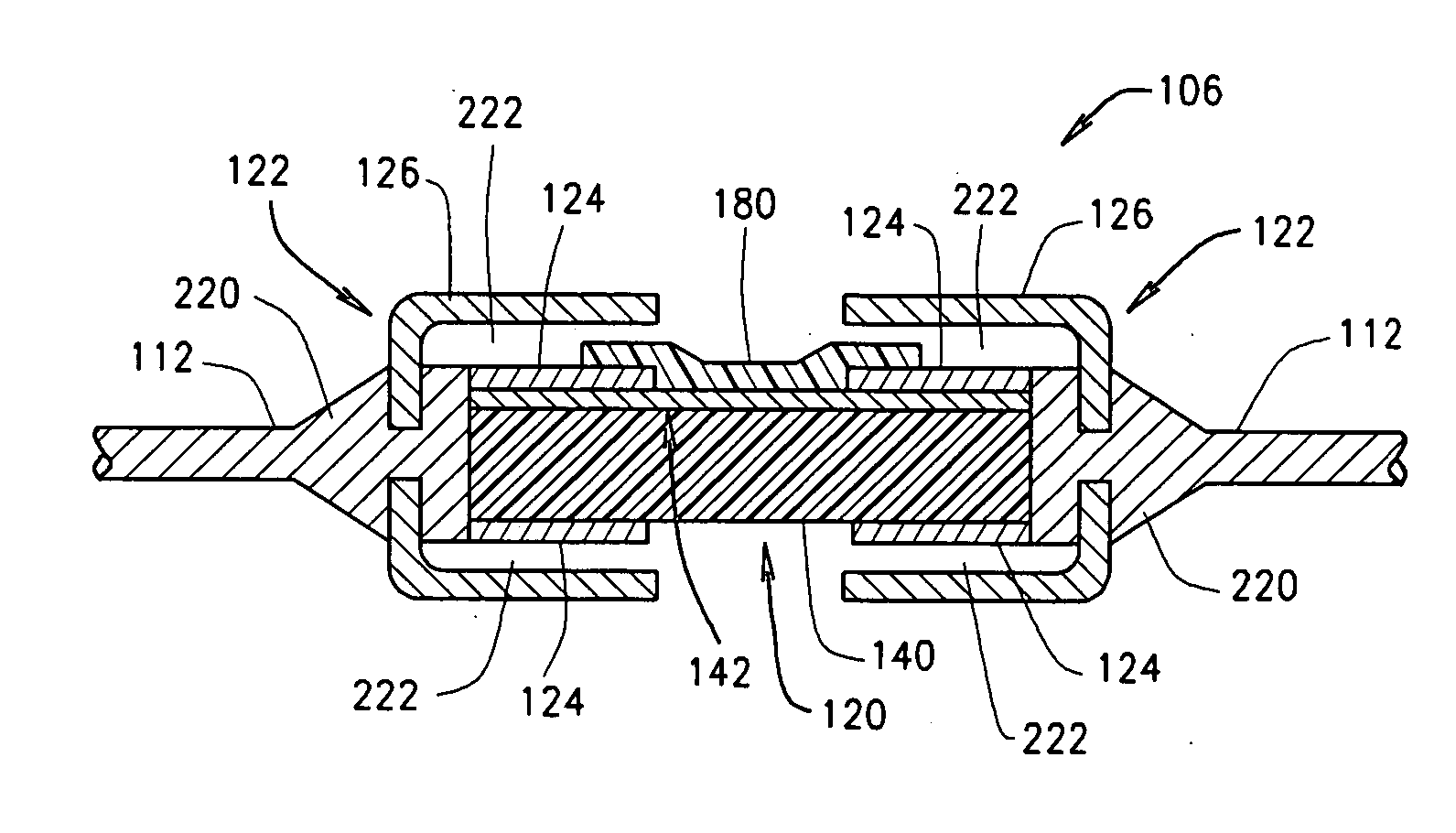
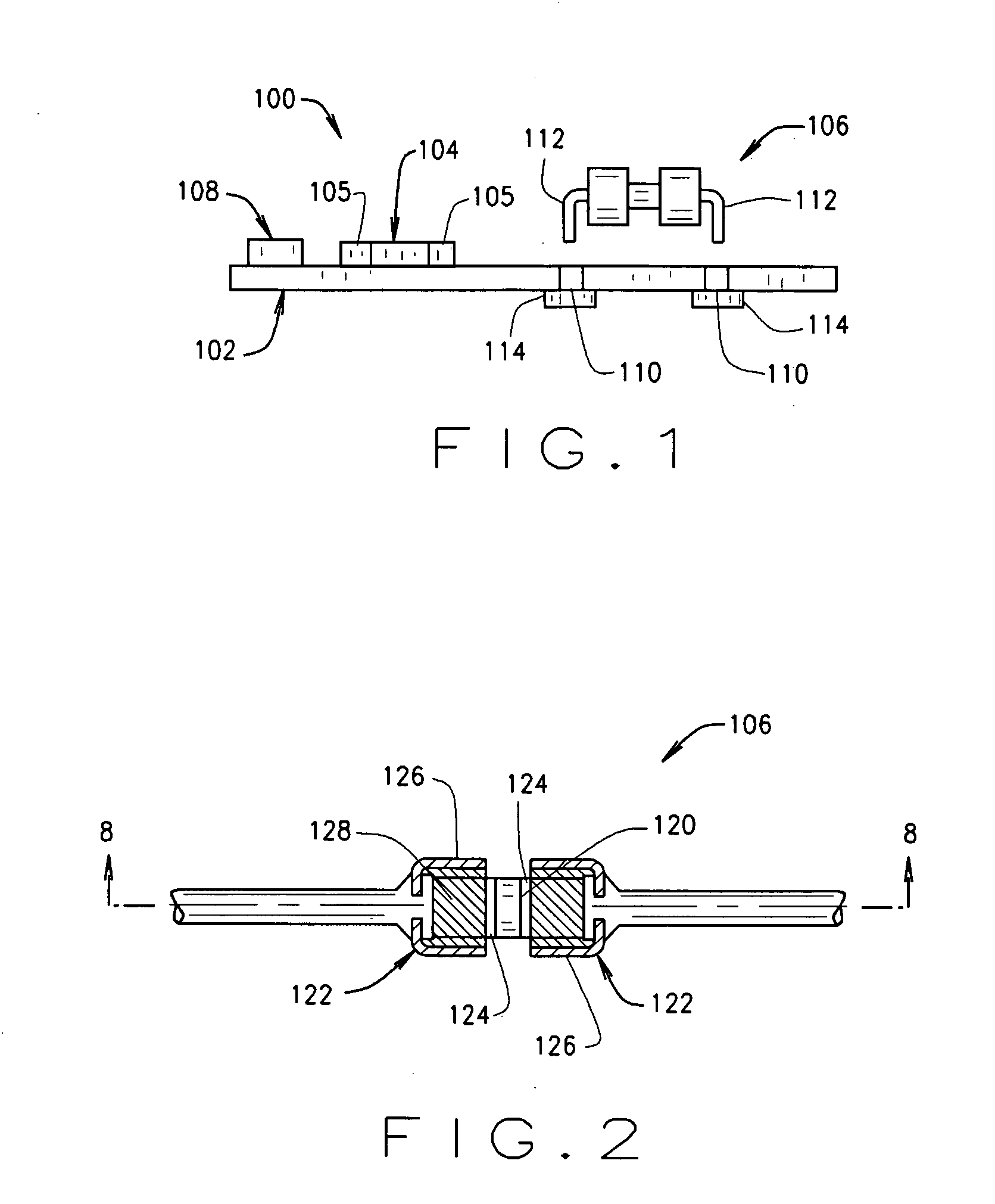
[0021]FIG. 1 is a side elevational schematic of a circuit board system 100 including a circuit board 102, a first subminiature circuit protector in the form of a surface mounted chip fuse 104, and a second subminiature circuit protector in the form of a leaded chip fuse 106 according to the present invention.

[0022] The circuit board 102 is fabricated from known materials and includes conductive pads, traces, etc. (not shown in FIG. 1) which interconnects electrical components 108 and associated circuitry. In one embodiment, the circuit board 102 is configured for testing components 108, such as, for example, memory chips or other components, including but not limited to burn-in testing of the components. In such an embodiment, the circuit board 102 may include a large number of surface mounted chip fuses 104 each protecting component sockets (not shown in FIG. 1) associated with the components 108 on the board 102. Thus, a large number of components may be tested simultaneously on ...


PUM


Abstract

A chip fuse includes a substrate, a fuse element extending on the substrate, and first and second wire leads coupled to the fuse element. Contact pads may extend over portions of the fuse element and establish electrical connection to the first and second leads. A conductive medium such as solder encircles the substrate to securely form a mechanical and electrical connection to the leads.

Description

BACKGROUND OF THE INVENTION [0001] This invention relates generally to fuses, and more particularly to chip fuses for protecting electronic devices from damaging electrical currents. [0002] Fuses are widely used as overcurrent protection devices to prevent costly damage to electrical circuits. Typically, fuse terminals or contacts form an electrical connection between an electrical power source and an electrical component or a combination of components arranged in an electrical circuit. One or more fusible links or elements, or a fuse element assembly, is connected between the fuse terminals or contacts, so that when electrical current through the fuse exceeds a predetermined threshold, the fusible elements melt, disintegrate, sever, or otherwise open the circuit associated with the fuse to prevent electrical component damage. [0003] A proliferation of electronic devices in recent times has resulted in increased demands on fusing technology. For example, a conventional fuse for elec...

Claims


Application Information

Patent Timeline
IPC IPC(8): H01L29/00
CPCH01H69/022H01H85/0411H01H85/046H01H85/143H01H2069/025H01H2085/0412H01H2085/266H05K3/3426H05K2201/10181H05K2201/10583H05K2201/10651H01L24/01Y02P70/50
Inventor SPAUNHORST, VERNON RAYMOND
Owner COOPER TECH CO
Why Eureka
Try Eureka