Method and apparatus for identifying feedback in a circuit

Active Publication Date: 2006-09-28
INMUSIC BRANDS
View PDF13 Cites 77 Cited by
  • Summary
  • Abstract
  • Description
  • Claims
  • Application Information

AI Technical Summary

Benefits of technology

[0010] The present invention overcomes the problems found in the prior art, of not adequately distinguishing desirable sounds from feedback, by using the characteristics of feedback (i.e., growth characteristics over time), instead of analyzing harmonically related frequencies (in real-time only) to discriminate feedback. First, it monitors the magnitude growth of constant frequency components to identify potential feedback. In addition to consistent frequencies that grow over time being identified as potential feedback, consistent frequencies with no significant magnitude change are identified as potential feedback based on their lack of dynamics, relative strength and duratio

Problems solved by technology

However, feedback frequencies will decay within a finite amount of time coincident with the placement of the test notch filter.
This kind of harmonically related feedback can occur naturally in a

Method used


Image

  • Method and apparatus for identifying feedback in a circuit
  • Method and apparatus for identifying feedback in a circuit
  • Method and apparatus for identifying feedback in a circuit

Examples


Embodiment Construction

[0020] The following discussion is presented to enable a person skilled in the art to make and use the invention. The general principles described herein may be applied to embodiments and applications other than those detailed above without departing from the spirit and scope of the present invention. The present invention is not intended to be limited to the embodiments shown, but is to be accorded the widest scope consistent with the principles and features disclosed or suggested herein.

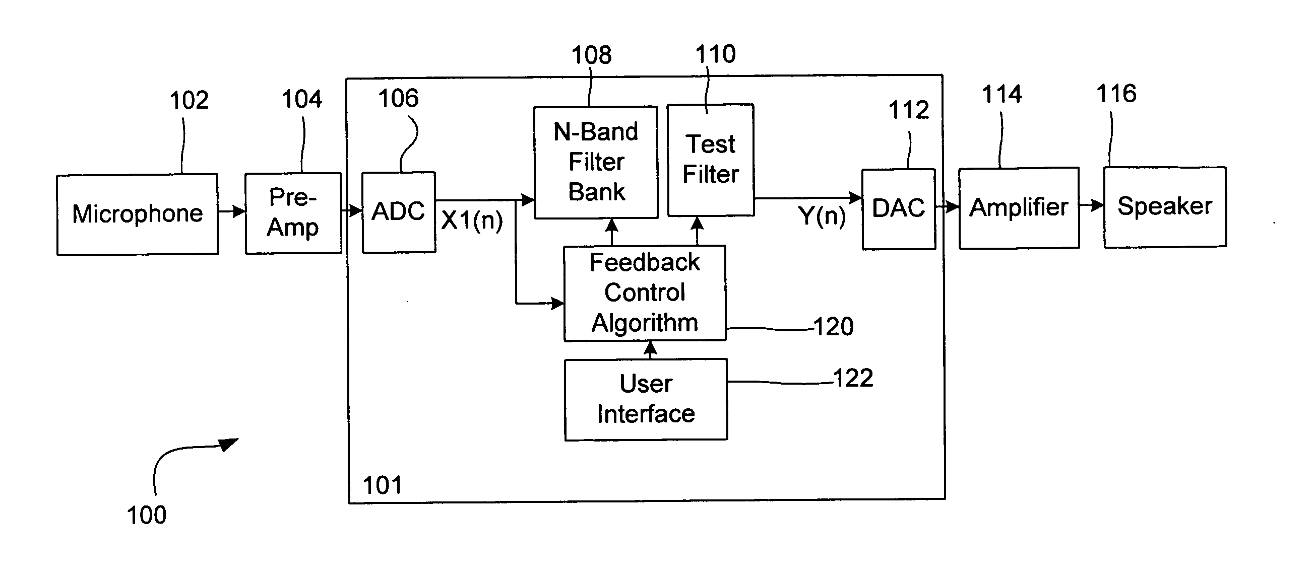
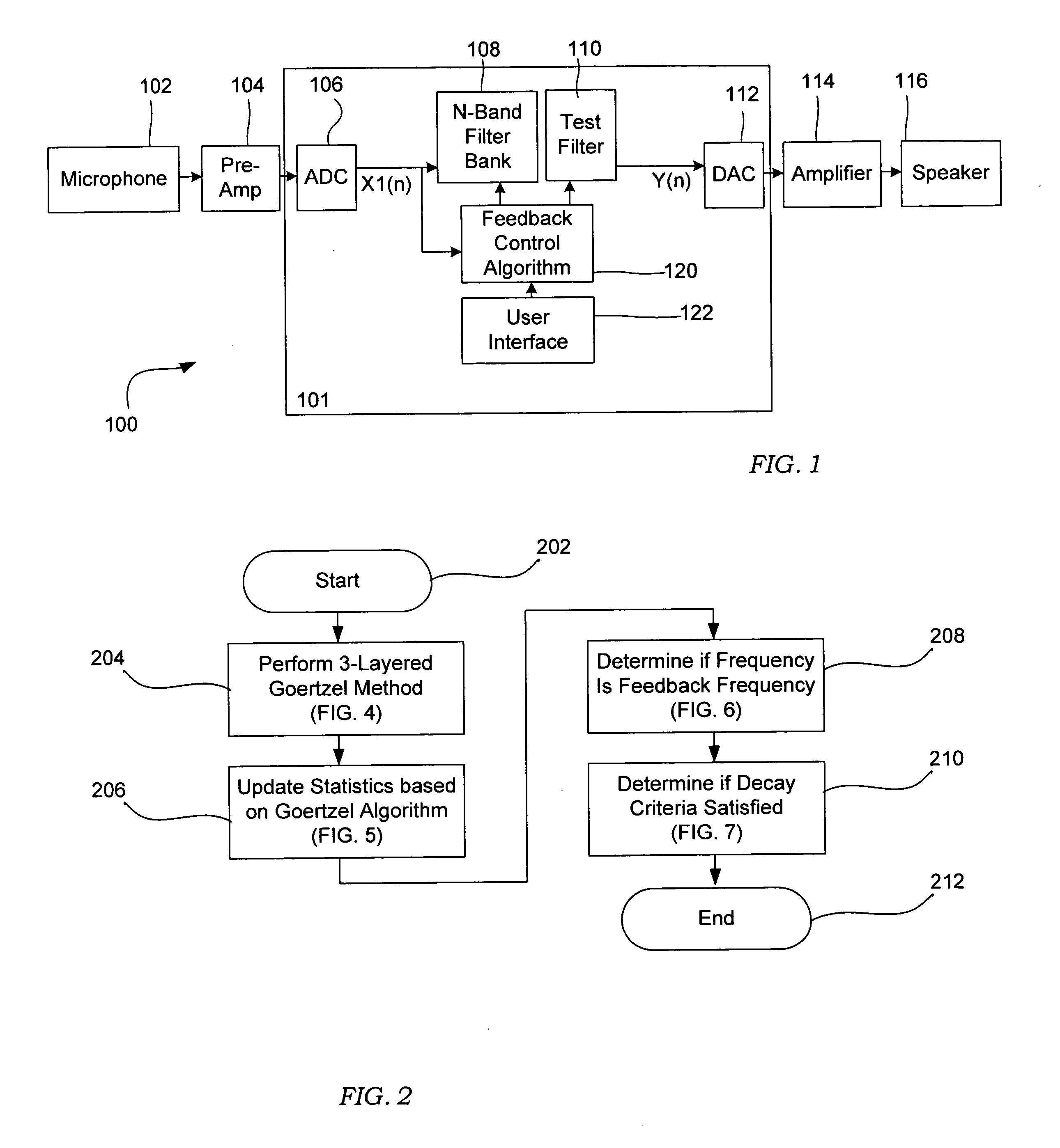
[0021]FIG. 1 shows a block diagram of feedback suppression circuit 101 as typically embodied within a sound amplification system 100 according to an embodiment of the invention. The sound amplification system 100 includes a number of components that may or may not be present in conjunction with the feedback suppression circuit 101. As such, the system described herein with respect to FIG. 1 is for exemplary purposes only and any of the described components need not be present in a feedback suppres...


PUM


Abstract

A system and method for analyzing a signal to monitor the dynamics of its magnitude and frequency characteristics over time. An electronic circuit for identifying feedback in an audio signal, formed in accordance with embodiments of the invention may comprise a feedback control block operable to determine a candidate frequency having potential feedback such that the feedback control block is further operable to perform an iterative analysis of the magnitude of the audio signal at the candidate frequency to determine the growth characteristics of the signal. The electronic circuit may further include a test filter block operable to deploy a test filter at a candidate frequency and a permanent filter block operable to deploy a permanent filter at the candidate frequency if the feedback control block determines that the growth characteristics of the signal at the candidate frequency comprises feedback characteristics after the test filter has been deployed.

Description

CROSS REFERENCE TO RELATED APPLICATION [0001] This application claims priority from U.S. Provisional Application 60 / 660,667 titled, “FEEDBACK SUPPRESSOR METHOD AND APPARATUS,” which was filed on Mar. 11, 2005, and which is incorporated by reference.BACKGROUND OF THE INVENTION [0002] Acoustic feedback is a common problem encountered in any typical closed loop audio amplification system. Generally speaking, feedback arises in an amplification system at frequencies where the loop gain of the electronic circuit is greater then or equal to unity and the system phase is positively reinforced such that particular frequencies may grow uncontrollably. In such a system, feedback will occur at the specific frequencies that satisfy these specific gain and phase criteria. The magnitude of the feedback frequencies will grow at a rate that is determined by the gain at those frequencies and a delay associated with various parameters of the amplification system. Once feedback instability is initiate...

Claims


Application Information

Patent Timeline
IPC IPC(8): H04B15/00
CPCH04R3/02
Inventor TROXEL, DANA
Owner INMUSIC BRANDS
Why Eureka
Try Eureka