Fan and shroud assembly

a technology of fan and shroud, which is applied in the direction of wind motors with parallel air flow, wind motors with perpendicular air flow, liquid fuel engine components, etc., can solve the problems of insufficient noise reduction and increased noise generated by fan and shroud assemblies, and achieve the effect of increasing the noise reduction

Inactive Publication Date: 2006-09-28
HANON SYST
View PDF11 Cites 53 Cited by
  • Summary
  • Abstract
  • Description
  • Claims
  • Application Information

AI Technical Summary

Benefits of technology

[0011] Accordingly, the present invention has been made to solve the above problems occurring in the prior art, and it is an object of the present invention to provide a fan and shroud assembly, whi

Problems solved by technology

Such shroud having the swirl preventing saw teeth can reduce noise, but noise generated from the fan and shroud assembly is more increased when noise ge

Method used


Image

  • Fan and shroud assembly
  • Fan and shroud assembly
  • Fan and shroud assembly

Examples


Embodiment Construction

[0026] Reference will be now made in detail to the preferred embodiment of the present invention with reference to the attached drawings. Terms and words used in this specification and claims should be interpreted as meaning and concept corresponding to the technical idea of the present invention based on the principle that the inventor can properly define the concept of words to explain the inventor's invention in the best way.

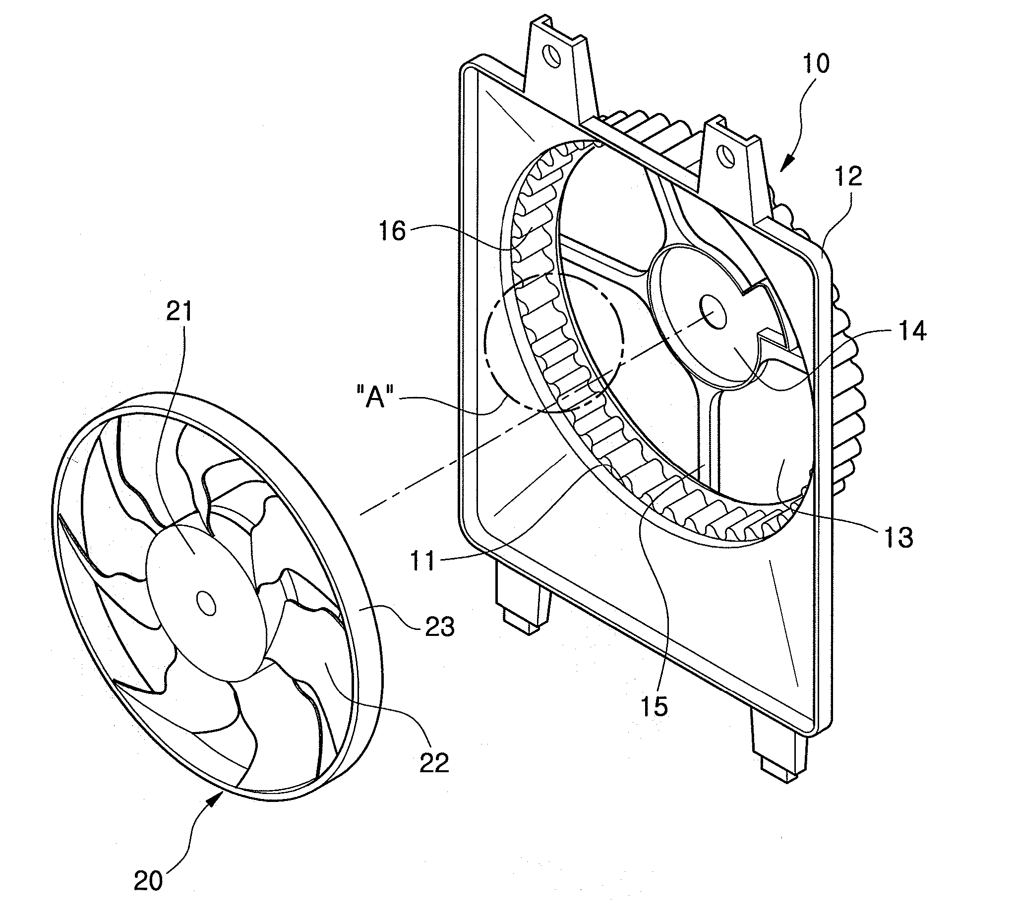
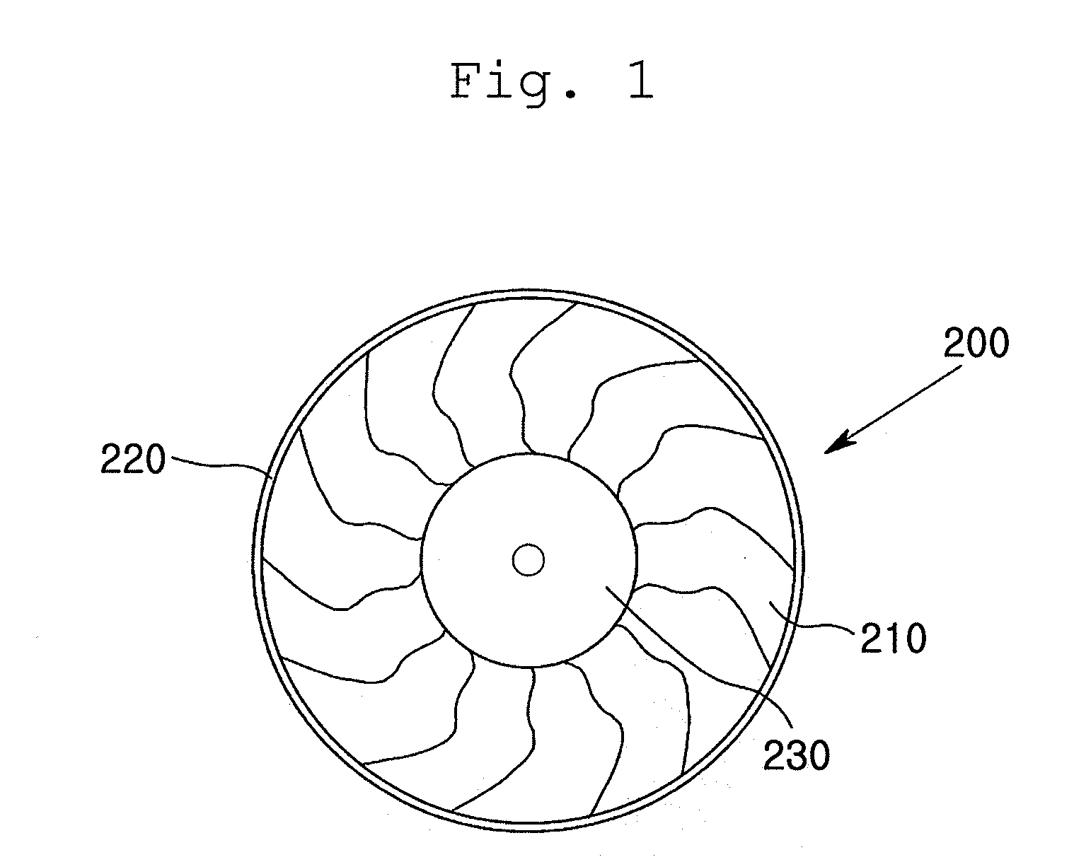
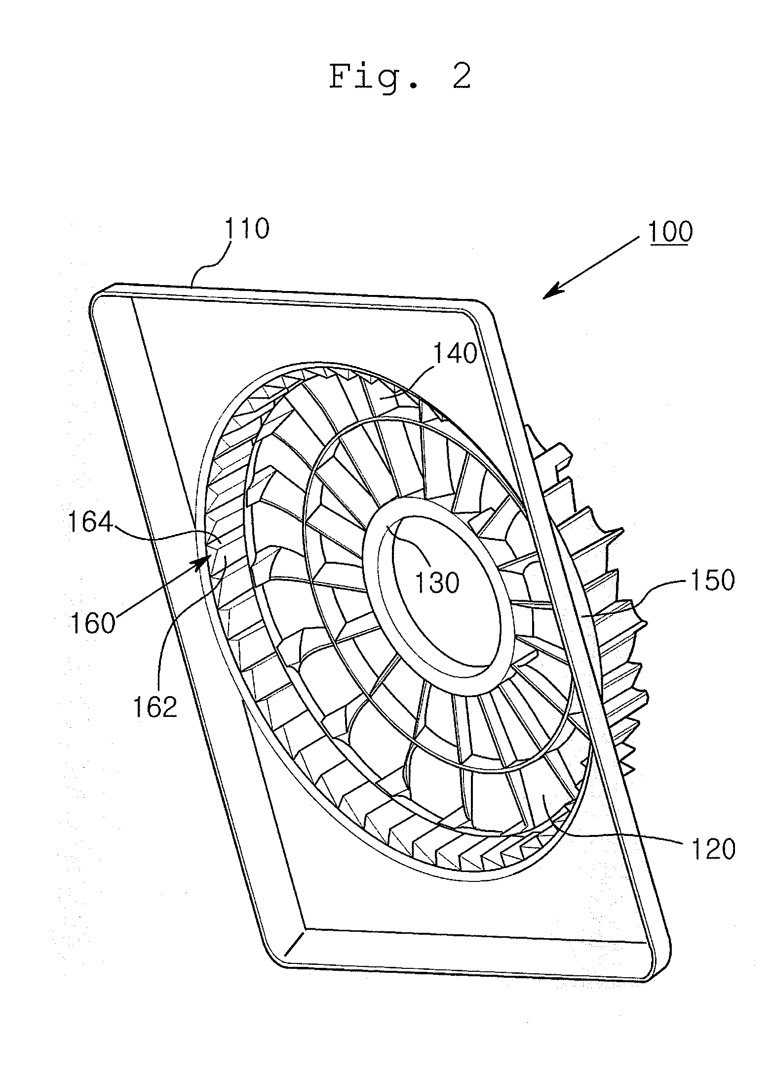
[0027]FIG. 5 is a front view of a fan and shroud assembly according to the present invention, FIG. 6 is an exploded perspective view of a fan and a shroud according to the present invention, FIG. 7 is a detailed view of an “A” part of FIG. 6, FIG. 8 is a perspective view of the shroud according to the present invention, and FIG. 9 is a view showing dimensions and arrangement of round corrugation formed on the shroud seen from a “B” part of FIG. 8.

[0028] The fan and shroud assembly according to the present invention comprises a fan 20 having a hub 21 rotatin...


PUM


Abstract

Disclosed herein is a fan and shroud assembly comprising: a fan having a hub rotating on a shaft and a plurality of blades extending outward from the hub; and a shroud surrounding the fan for controlling air blast by rotation of the fan, wherein the shroud comprises: a guide ring part spaced apart at a predetermined interval from the periphery of the fan which connects ends of the blades; and swirl preventing means formed on the guide ring part for preventing swirling airflow along the periphery of the fan connecting the ends of the blades. The fan and shroud assembly can minimize generation of swirling airflow and backflow and provide improved noise-reduction effect.

Description

BACKGROUND OF THE INVENTION [0001] 1. Field of the Invention [0002] The present invention relates to a fan and shroud assembly used for an air blast in an air conditioner of a car, and more particularly, to a fan and shroud assembly which can effectively reduce noise by controlling generation of swirling airflow and backflow during the air blast by rotation of a fan. [0003] 2. Background Art [0004] In general, an air conditioner for a car comprises a radiator, and an axial fan for cooling heat exchange medium flowing through a heat exchanger such as a condenser. As shown in FIG. 1, the axial fan 200 generally comprises a hub 230 connected with a shaft of a driving source such as a motor, and a plurality of blades 210 radially arranged on the outer periphery of the hub 230. The axial fan 200 may further include a fan band 220 connecting ends of the blades 210 to prevent transformation of the blades 210. Therefore, air can be axially blown by the blades 210 while the axial fan 200 is ...

Claims


Application Information

Patent Timeline
IPC IPC(8): F04D19/00
CPCF04D29/164F04D29/545F04D29/667F04D29/326G01N1/2258G01N1/2205F01N3/021G01N2001/2261
Inventor PARK, SE-YOUNG
Owner HANON SYST
Why Eureka
Try Eureka