
Communication mode controlling method, mobile communication system, radio network controller, base station, and mobile communication terminal

a communication mode and control method technology, applied in the field of mobile communication system, can solve the problems of not disclosing the process of switching between the autonomous mode and the scheduling mode under other communication conditions, and the inability of the base station to demodulate the transmission signal, and achieve the effect of efficient data communication

Inactive Publication Date: 2006-09-28
MITSUBISHI ELECTRIC CORP
View PDF2 Cites 27 Cited by
  • Summary
  • Abstract
  • Description
  • Claims
  • Application Information

AI Technical Summary

Benefits of technology

The present invention provides a communication mode controlling method for a mobile communication terminal to switch between an autonomous mode and a scheduling mode for data communications with a base station. The method determines the communication mode based on the amount of interference and communication characteristics, and the mobile communication terminal informs the base station of the amount of communication data. This allows for efficient data communications based on changes in the noise rise caused by changes in the load of communications between the base station and the mobile communication terminal.

Problems solved by technology

However, although the above-mentioned related art reference discloses application of a switching to either the autonomous mode or the scheduling mode based on the amount of data to the above-mentioned related art data communication method, it does not disclose any process of switching between the autonomous mode and the scheduling mode under other communication conditions.
In uplink packet communications using a CDMA method, when interference caused by a transmission signal from a wireless device exceeds the limit of a noise rise in a base station, the base station cannot demodulate the transmission signal.

Method used


Image

  • Communication mode controlling method, mobile communication system, radio network controller, base station, and mobile communication terminal
  • Communication mode controlling method, mobile communication system, radio network controller, base station, and mobile communication terminal
  • Communication mode controlling method, mobile communication system, radio network controller, base station, and mobile communication terminal

Examples


embodiment 1

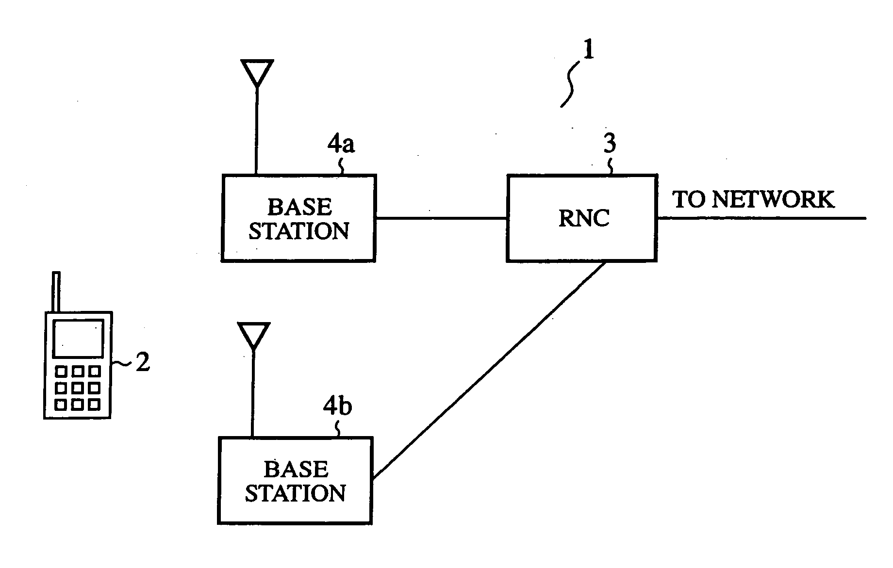
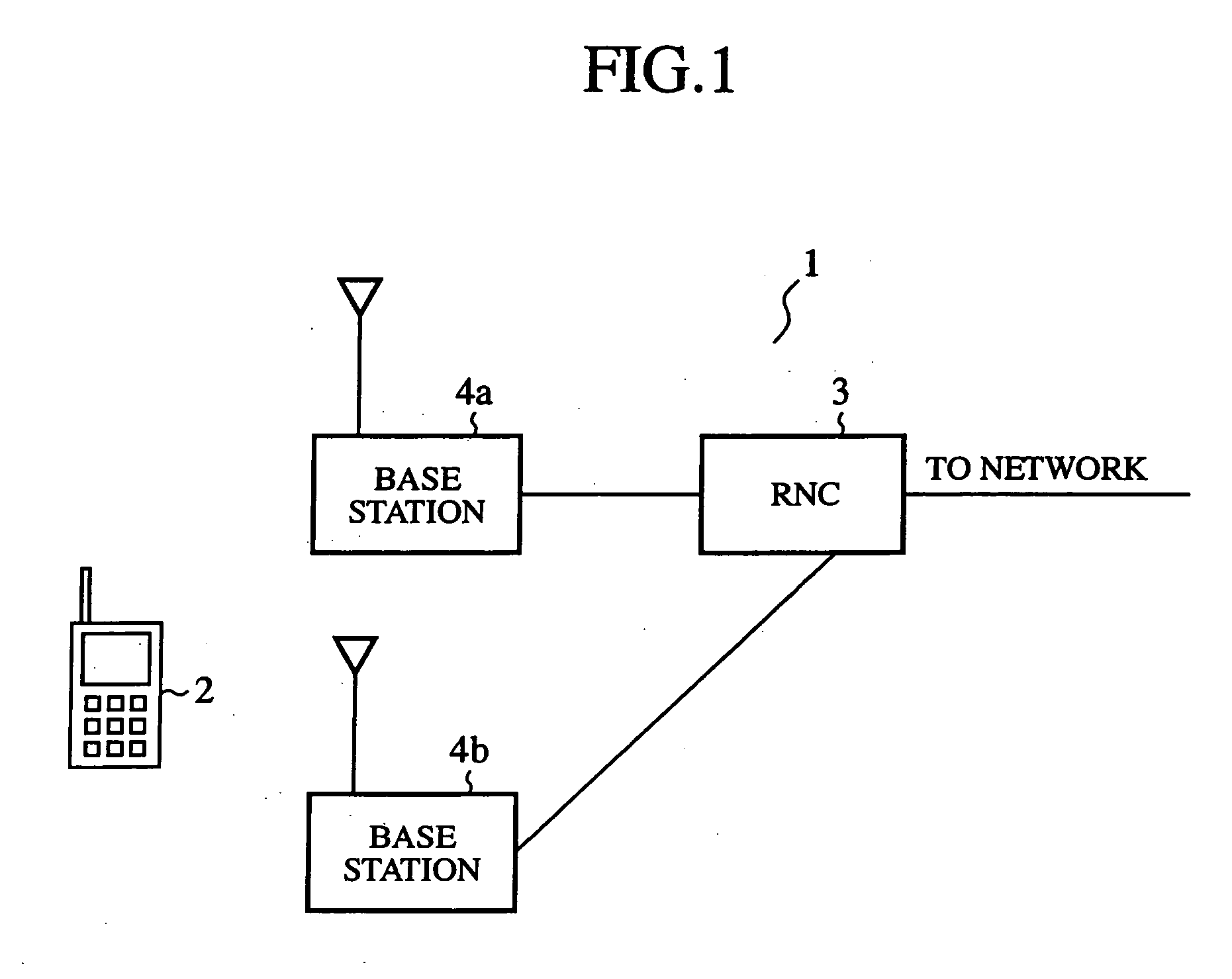
[0046]FIG. 1 is a diagram schematically showing the structure of a mobile communication system in accordance with embodiment 1 of the present invention. The mobile communication system 1 is provided with a mobile communication terminal 2 which the user uses, an RNC (Radio Network Controller) 3, and base stations 4a and 4b. The RNC 3 is disposed between a construction disposed on a side of a network, such as a public network, and the base stations 4a and 4b, and relays packet communications between them.

[0047] Thus, the system 1 is so constructed that the RNC 3 controls the two or more base stations 4a and 4b for the side of the network. As a result, in the system 1, a radio link which is called a soft handover can be established among the two or more base stations 4a and 4b for one terminal 2.

[0048] When the mobile communication system 1 is implemented using a W-CDMA (Wideband-Code Division Multiple Access) method, the mobile communication terminal 2 can be called UE (User Equipme...


PUM


Abstract

A communication mode which should be set to a mobile communication terminal having a function of switching between an autonomous mode and a scheduling mode is determined based on an amount of interference in each of the communication modes in the cell of a base station, and / or communication characteristics of each of the communication modes, and a signal indicating an amount of communication data notified from the mobile communication terminal. The base station then notifies the determined communication mode to the mobile communication terminal.

Description

[0001] The present divisional application claims the benefit under 35 U.S.C. §120 of application Ser. No. 10 / 572,599, filed Mar. 20, 2006, and PCT / JP03 / 12552, filed Sep. 30, 2003, the disclosure of each is herein incorporated by reference.FIELD OF THE INVENTION [0002] The present invention relates to a mobile communication system with CDMA (Code Division Multiple Access). More particularly, it relates to a communication mode controlling method of, a mobile communication system for, and an RNC (Radio Network Controller) for controlling a switching between communication modes according to the status of communications between a base station and a mobile communication terminal, the base station, and the mobile communication terminal. BACKGROUND OF THE INVENTION [0003] Related art wireless multi-mode data communication methods include a method (for example, refer to JP,2002-369261,A) of switching between an autonomous mode in which data are transmitted and received autonomously, and a so...

Claims


Application Information

Patent Timeline
Patent Type & Authority Applications(United States)
IPC IPC(8): H04B1/00H04Q7/00H04B7/26H04W28/14H04W8/24H04W28/00H04W72/54H04W74/02
CPCH04W8/245H04W28/14H04W72/1226H04W28/16H04B1/1027H04B1/406H04W72/1252H04W72/54H04W72/52
Inventor WAKABAYASHI, HIDEJI
Owner MITSUBISHI ELECTRIC CORP
Learn More