
Artificial hip joint without a shaft

a technology of artificial hip joint and shaft, which is applied in the field of artificial hip joint without shaft, can solve the problems of sheet steel not being completely integrated with the femur in order to protect the femur, patients suffering from pain, and application becoming impractical

Inactive Publication Date: 2006-09-28
CHIENG POONUNG
View PDF21 Cites 24 Cited by
  • Summary
  • Abstract
  • Description
  • Claims
  • Application Information

AI Technical Summary

Benefits of technology

[0006] Therefore, it is the primary objective of the present invention to overcome the foregoing shortcomings by providing an artificial hip joint without a shaft that can improve the fixing of the femur neck and enhance the strength of the femur neck, and the artificial hip joint without a shaft can be integrated with the femur of a patient.
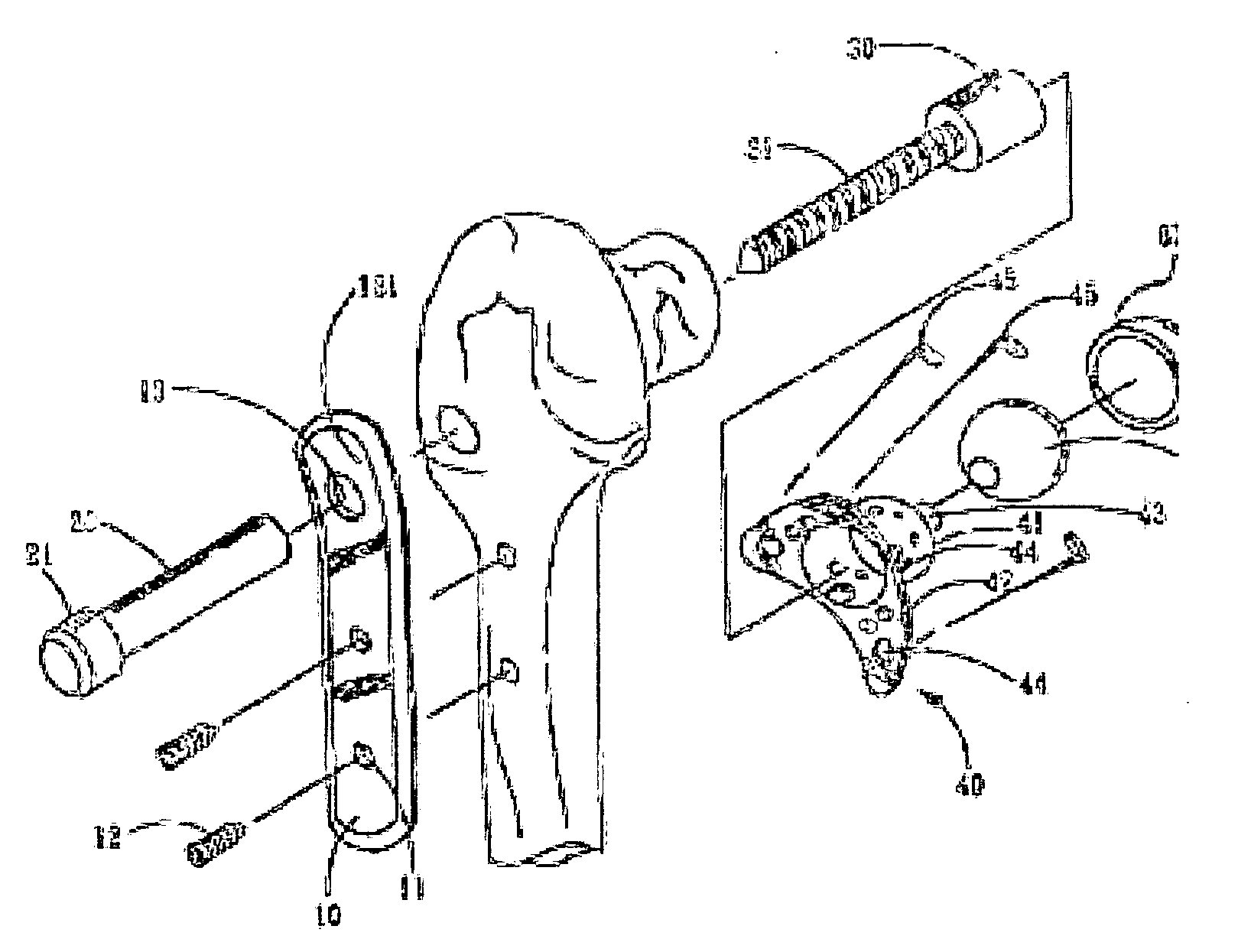
[0008] With the fixing of the center bone screw, the femur neck protecting device can be attached closely onto the surface of the femur to protect the cut or damaged femur head and improve the rigidity and stabilization of a weak femur head under the protection of the enhancing bone plate.
[0010] Such arrangement can protect the femur neck from being hurt again, and the newly grown blood vessels and bone scars can pass through the hole and cover onto a main body so as to integrally integrate the main body with the femur.

Problems solved by technology

However, the design of such a traditional structure has the shortcomings of being unable to stably cover the sheet steel and the newly grown blood vessels and bone scars cannot cover the sheet steel effectively, so that the sheet steel cannot be integrated completely with the femur in order to protect the femur.
Further, the application becomes impractical, and patients suffer from pains.
Furthermore, the femur neck protecting device does not come with a device to protect the femur, and thus will slow down the recovery of a patient, particularly for patients having osteoporosis.

Method used


Image

  • Artificial hip joint without a shaft
  • Artificial hip joint without a shaft
  • Artificial hip joint without a shaft

Examples


Embodiment Construction

[0014] The above and other objects, features and advantages of the present invention will become apparent from the following detailed description taken with the accompanying drawing.

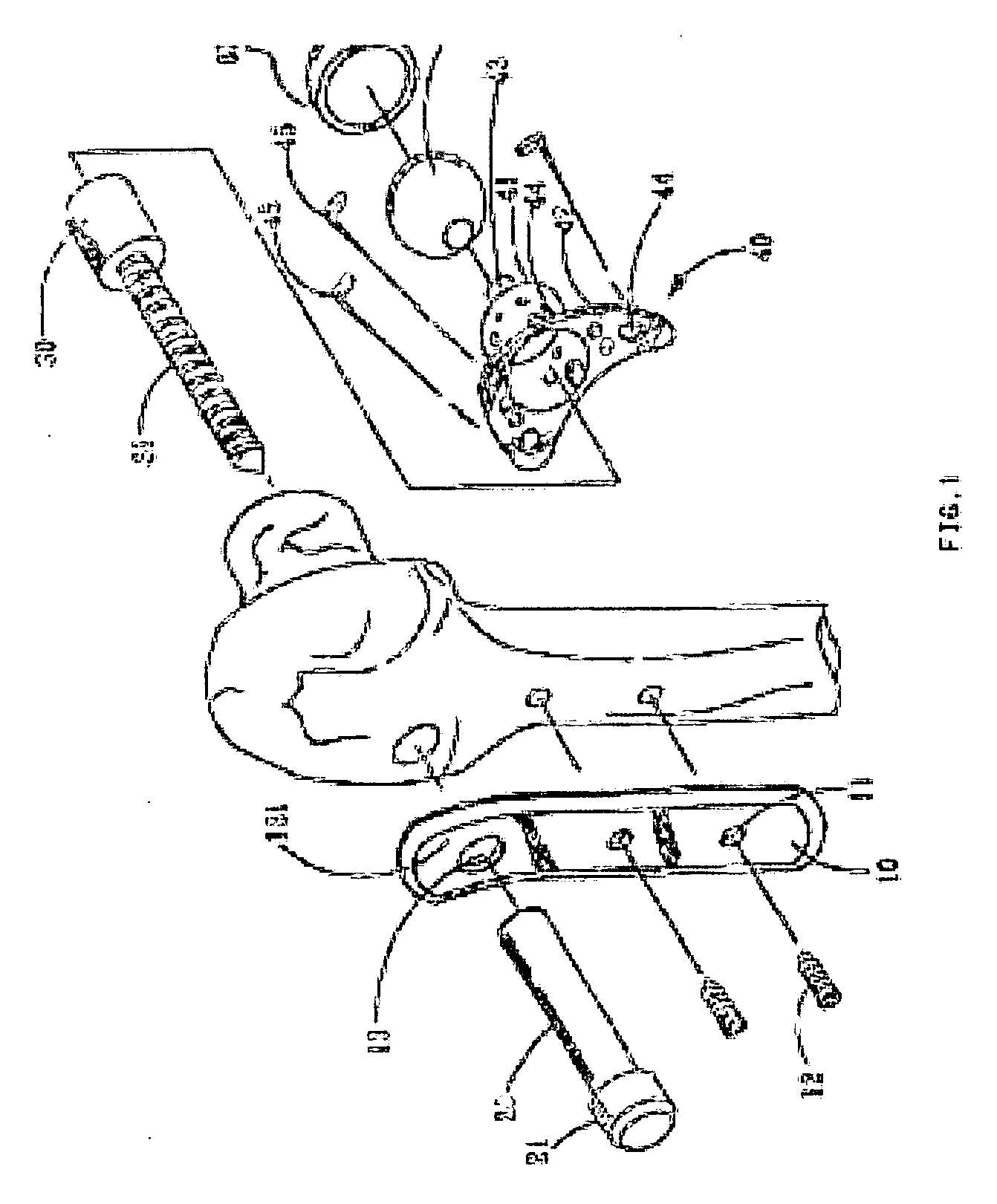
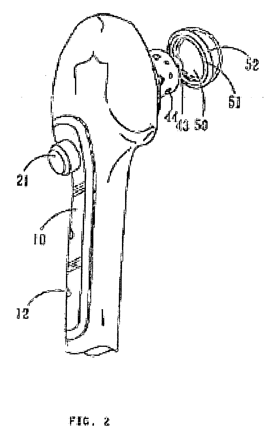
[0015] Referring to FIGS. 1 to 3 for the artificial hip joint without a shaft of the present invention, the device comprises an enhancing bone plate 10, and the enhancing bone plate 10 includes more than one hole 111, and the holes 111 separately include a fixing element 12 which is a screw in this preferred embodiment. The enhancing bone plate 10 includes an opening hole 13 disposed at a predetermined position, and an enhancing bone screw 20 passes through the opening hole 13, and the enhancing bone screw 20 is a sleeve in this preferred embodiment. The enhancing bone screw 20 has a head section 21 disposed at an end having an area larger than the area of the opening hole 13, so that when the enhancing bone screw 20 is passed into the opening hole 13, the enhancing bone screw 20 will not be sunk into t...


PUM


Abstract

The invention provides an artificial hip joint without a shaft which includes an enhancing bone plate for supporting the femur, the plate having more than one hole on its surface, fixing elements for fixing the plate on the surface of the femur extending through these holes respectively; an enhancing bone screw which is expended through the plate and the femur; a center bone screw which is screwed with the enhancing bone screw; the other end of the center bone screw extending out of the femur neck; and a femur neck protecting device for protecting the femur neck, the device being fixed on the end which is not connected with the enhancing bone screw. With the fixation of the center bone screw, the protecting device can ride against the surface of the femur tightly so that it can protect the remaining bone cutting off the diseased or damaged. It can also enhance the rigidity and stabilization of the bone which is not well in function by the support of the enhancing bone plate.

Description

BACKGROUND OF THE INVENTION [0001] 1. Field of the Invention [0002] The present invention relates to a device for connecting a damaged or broken femur head, more particularly to an artificial hip joint without a shaft. [0003] 2. Description of the Related Art [0004] For the traditional treatment of a fractured or broken femur neck, the damaged or broken part is generally resumed to its original position and covered by a sheet steel, and then two nails are installed into the femur for fixing the sheet steel. However, the design of such a traditional structure has the shortcomings of being unable to stably cover the sheet steel and the newly grown blood vessels and bone scars cannot cover the sheet steel effectively, so that the sheet steel cannot be integrated completely with the femur in order to protect the femur. The force exerted on the sheet steel at the broken femur is very limited, and thus the sheet steel will be separated from the femur easily. Further, the application becom...

Claims


Application Information

Patent Timeline
IPC IPC(8): A61F2/30A61B17/74A61B17/76A61B17/86A61B19/00A61F2/32A61F2/34A61F2/36
CPCA61B17/86A61B2019/481A61F2/32A61F2/3601A61F2002/30574A61F2002/30787A61F2002/3401A61F2002/3611A61F2002/3625A61F2002/365A61B2090/08021
Inventor CHIENG, POONUNG
Owner CHIENG POONUNG
Learn More