Rubber crawler traveling device
a technology of traveling device and rubber track, which is applied in the direction of transportation and packaging, vehicle maintenance, vehicle cleaning, etc., can solve the problems of increasing uneven wear of guides, decreasing increasing so as to improve the life of rubber tracks and reduce the even wear of guides
- Summary
- Abstract
- Description
- Claims
- Application Information
AI Technical Summary
Benefits of technology
Problems solved by technology
Method used
Image

Examples
first embodiment
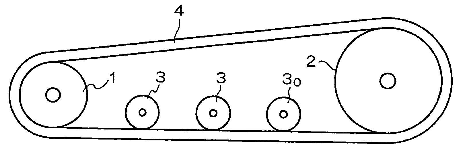
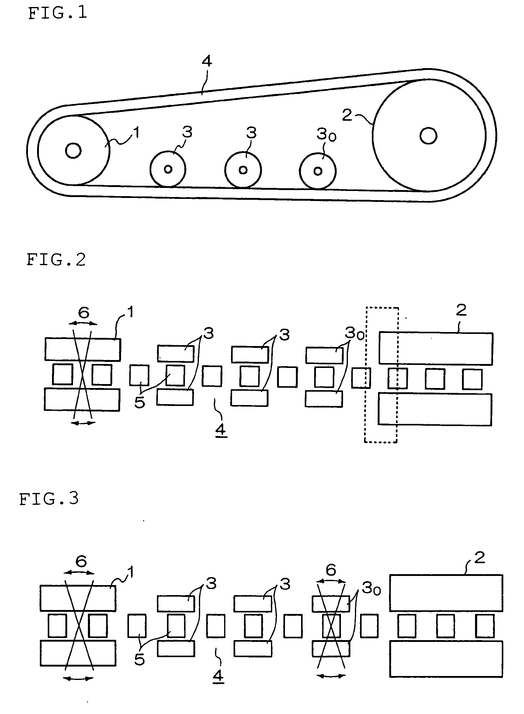
[0025] The present invention will be described below in more detail with reference to the drawings. A conceptual view of the rubber track traveling device of the present invention is the same as FIG. 1. FIG. 3 is a view showing the state of the rubber track traveling device on a ground-contact surface. Reference numerals 1, 2, 3, 4, 5 and 6 in the drawings are defined as described above, and description thereof will be omitted.
[0026] An embodiment of the present invention is a structure in which the adjustment mechanism 6 (for adjustment in directions indicated by the arrows) is provided at the idler wheels 1 and at least wheels 30 closest to the drive wheels 2. Because of this structure, straight traveling and the like of the rubber track are adjusted twice, i.e., at the idler wheels 1 and the wheels 30. As a result, the rubber track contacts the drive wheels 2 with a desirable orientation, thereby significantly reducing (uneven) wear of the rubber track.
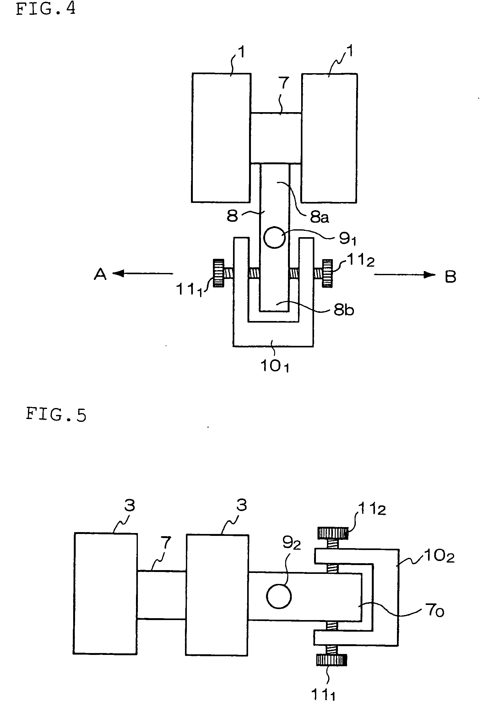
[0027]FIG. 4 is a view sh...
second embodiment
[0029]FIG. 5 is a view showing a second embodiment of the adjustment mechanism 6. In the second embodiment, the shaft 7 supporting the wheels 3 (30) is extended, and a horizontal portion (extended portion) 70 thereof is supported by a shaft 92 so as to be rotatable relative to a vehicle. The horizontal portion 70 is accommodated in a frame 102 as in the first embodiment. The adjusting screws 111, 112 are adjusted so as to change the orientation of the horizontal portion 70, whereby the orientation of the wheels 3 is adjusted. A specific process for adjustment is carried out as described in the previous paragraph. In this case, two pairs of the adjusting screws, i.e., the adjusting screws 111, 112 and adjusting screws 113, 114, are provided to enable fine adjustment of the orientation of a frame 12, which also enables fine adjustment of the orientation of the wheels 3, 3.
third embodiment
[0030]FIGS. 6 and 7 are views showing a third specific embodiment of the adjustment mechanism 6. In the third embodiment, a vertical shaft 93 is provided at the shaft 7 which supports the wheels 30 closest to the drive wheels 2. A connecting member (the frame 12 in this embodiment) is connected to the vertical shaft 93 and supported by a frame 13, which accommodates the frame 12 and is fixed to a vehicle, so as to be rotatable relative to the vehicle. The adjusting screws 111, 112, 113 and 114 are provided at sides of the frame 13 and adjusted so as to position the frame 12, whereby the orientation of the wheels 3 is adjusted. A specific process for adjustment is carried out as described in the previous paragraph. In this case, two pairs of the adjusting screws, i.e., the adjusting screws 111, 112 and the adjusting screws 113, 114, are provided to enable fine adjustment of the orientation of the frame 12, which also enables fine adjustment of the orientation of the wheels 3, 3.
PUM
 Abstract
Description
Claims
Application Information
 - R&D
- Intellectual Property
- Life Sciences
- Materials
- Tech Scout
- Unparalleled Data Quality
- Higher Quality Content
- 60% Fewer Hallucinations
Browse by: Latest US Patents, China's latest patents, Technical Efficacy Thesaurus, Application Domain, Technology Topic, Popular Technical Reports.
© 2025 PatSnap. All rights reserved.Legal|Privacy policy|Modern Slavery Act Transparency Statement|Sitemap|About US| Contact US: help@patsnap.com