Liquid crystal display device

a liquid crystal display and display device technology, applied in static indicating devices, non-linear optics, instruments, etc., can solve the problems of reducing the efficiency of light utilization (i.e., aperture ratio), and achieve the effect of improving the aperture ratio of pixels and improving the aperture ratio

Inactive Publication Date: 2006-10-05
PANASONIC LIQUID CRYSTAL DISPLAY CO LTD +1
View PDF17 Cites 22 Cited by
  • Summary
  • Abstract
  • Description
  • Claims
  • Application Information

AI Technical Summary

Benefits of technology

[0017] In one feature of the transflective LCD of the present invention, the aperture ratio is improved taking account of the positional relationship between the reflective regions and the color filters.
[0018] The present invention can provide a liquid crystal display which has both reflective and transmissive regions ...

Problems solved by technology

Consequently, there is the problem that the efficiency of utilization of ligh...

Method used


Image

  • Liquid crystal display device
  • Liquid crystal display device
  • Liquid crystal display device

Examples


Embodiment Construction

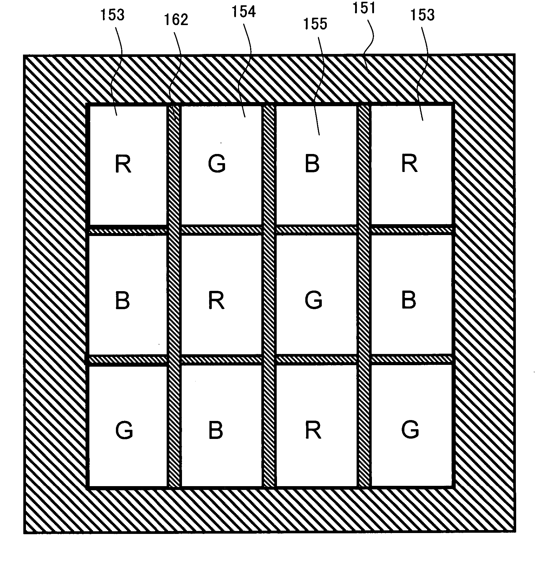
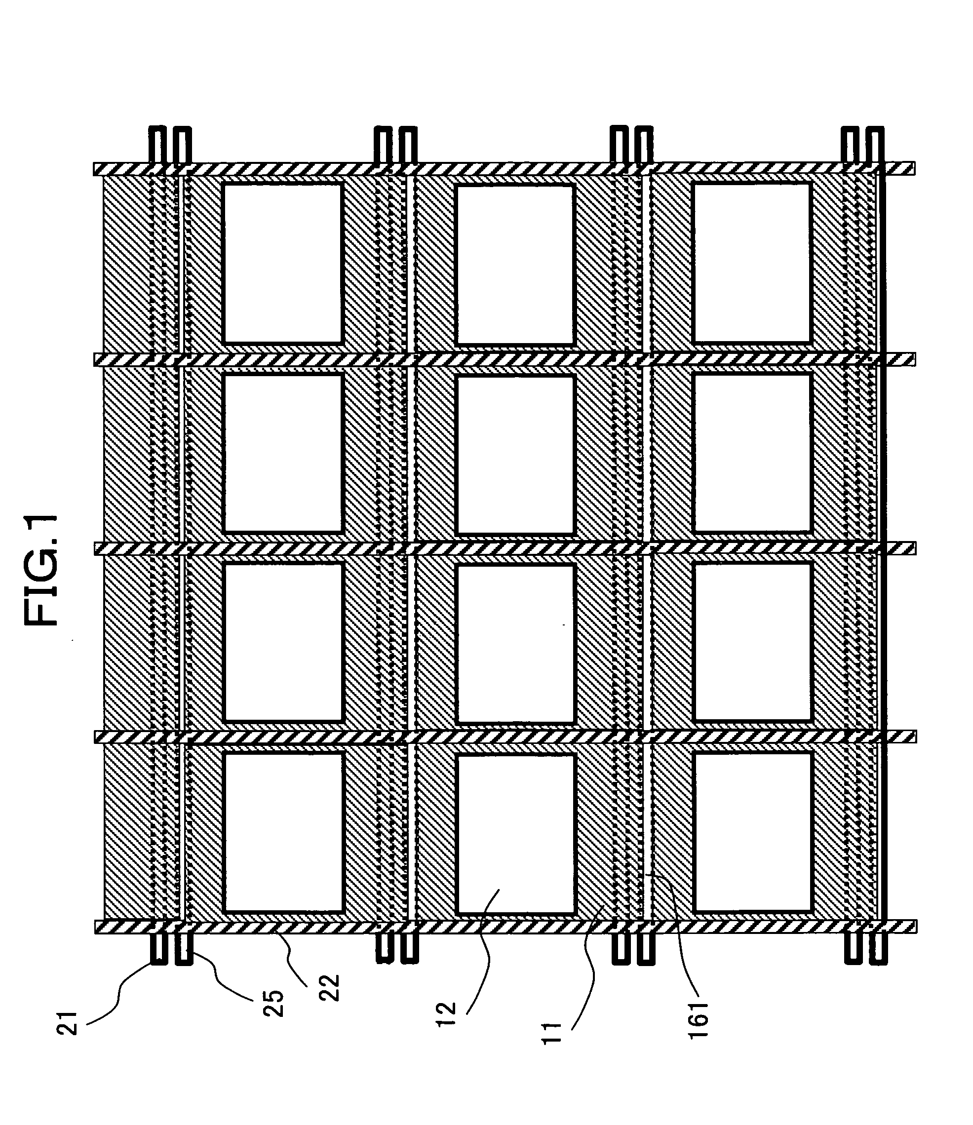
[0055]FIG. 1 is a plan view showing reflective regions 11 and transmissive regions 12 of pixels of a liquid crystal display according to the present invention. The liquid crystal display is equipped with a multiplicity of pixels arranged in a matrix. For ease of understanding, only some of the pixels of the display are shown in FIG. 1.

[0056] In FIG. 1, each area surrounded by gate signal lines (also referred to as scanning lines) 21 extending in the x-direction and juxtaposed in the y-direction and by drain signal lines (also referred to as video signal lines) 22 extending in the y-direction and juxtaposed in the x-direction is taken as a pixel region. The pixel region has the reflective region 11 and transmissive region 12.

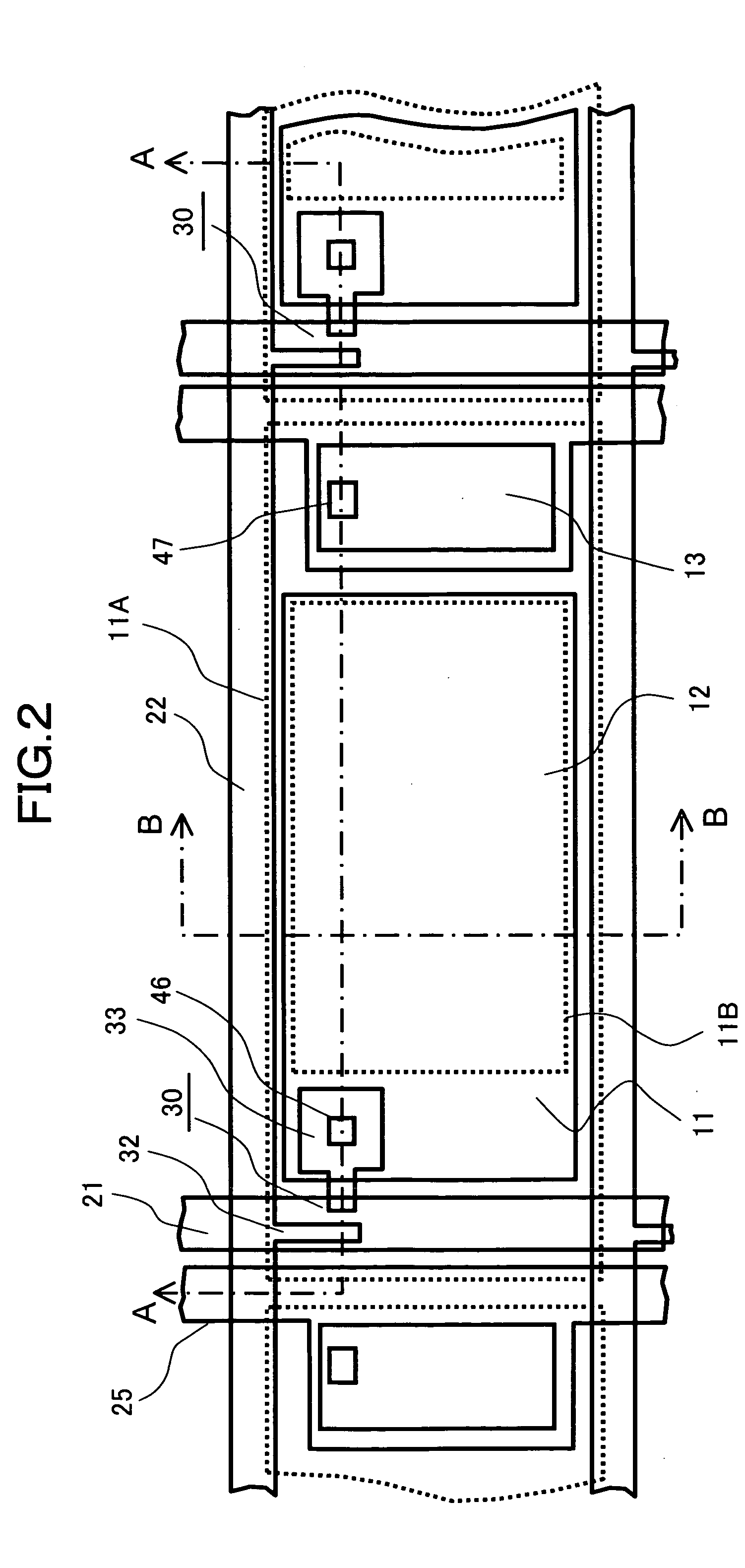
[0057] In FIG. 1, storage capacitor lines 25 are formed parallel to the gate signal lines 21. End portions of the reflective regions 11 extend beyond the gate signal lines 21 and overlap the storage capacitor lines 25. Furthermore, the end portions of the refle...


PUM


Abstract

There is disclosed a transflective liquid crystal display having pixels each including a reflective region and a transmissive region. The aperture ratio of the pixels can be enhanced. End portions of two adjacent color filters are overlapped to form an optically shielding portion for each pixel. The optically shielding portion and the reflective region cooperate to form an optically shielding film acting as a black matrix for the transmissive region. The aperture ratio is enhanced by improving the positional relationship between the reflective regions and the color filters.

Description

BACKGROUND OF THE INVENTION [0001] 1. Field of the Invention [0002] The present invention relates to a display device equipped with color filters and, more particularly, to a transflective liquid crystal display having a transmissive region and a reflective region within each one pixel. [0003] 2. Description of Related Art [0004] In recent years, so-called transflective liquid crystal displays (LCDs) operating in both reflective and transmissive display modes have been often used as display portions of mobile electronic devices. [0005] A transflective LCD has both transmissive and reflective regions within each one pixel. The transflective LCD operates either in a transmissive display mode in which light transmits through transmissive regions formed in pixels or in a reflective display mode in which light is reflected by reflective regions formed in the pixels. [0006] When the transflective liquid crystal display is used outdoors, the display is employed under bright ambient conditi...

Claims


Application Information

Patent Timeline
IPC IPC(8): G09G3/36
CPCG02F1/133512G02F1/133555G02F1/133514G02F1/1335
Inventor ISHIHARA, KATSUYOSHIYAMADA, HIRONOBU
Owner PANASONIC LIQUID CRYSTAL DISPLAY CO LTD
Why Eureka
Try Eureka