Liquid crystal display device, driving method of the liquid crystal display device, and electronic device employing the same device and the same method

Active Publication Date: 2009-01-08
SEMICON ENERGY LAB CO LTD
View PDF31 Cites 102 Cited by
  • Summary
  • Abstract
  • Description
  • Claims
  • Application Information

AI Technical Summary

Benefits of technology

[0072]In the present invention, viewing angle characteristics for a viewer can be improved by making liquid crystal molecules slanted to increase directions of alignment, and the viewing angle characteristics can also be improved by changing the transmittance of the liquid crystal molecules every frame. As a result, a liquid crystal display device which is capable of improving viewing angle characteristics, a driving method of the liquid crystal display device, and an electronic device including the liquid crystal display device can be provided.
[0073]Moreover, in the present

Problems solved by technology

However, as simply shown in Patent Document 1, by increasing the number of sub-pixels to increase directions of alignment of the liquid crystal molecules and impr

Method used


Image

  • Liquid crystal display device, driving method of the liquid crystal display device, and electronic device employing the same device and the same method
  • Liquid crystal display device, driving method of the liquid crystal display device, and electronic device employing the same device and the same method
  • Liquid crystal display device, driving method of the liquid crystal display device, and electronic device employing the same device and the same method

Examples


embodiment mode 1

[0166]First, a basic principle for describing the present invention will be mentioned in detail.

[0167]A plurality of pixels is provided in a display portion of a display device and is arranged in matrix as an example shown in FIG. 75. In FIG. 75, a plurality of pixels 7504 which is connected to a scanning line 7502 and a signal line 7503 is provided in a display portion 7501. One pixel includes one region or more regions (hereinafter, referred to as a sub-pixel). For example, as shown in FIG. 75, one pixel includes a first sub-pixel (sub-pixel A 7504A) and a second sub-pixel (sub-pixel B 7504B).

[0168]One pixel expresses grayscale of one pixel with the total amount of light to be transmitted through respective sub-pixels A and B. That is, the amount X of light to be transmitted corresponding to a level of grayscale expressed in one pixel is the sum of the amount XA of light to be transmitted through the sub-pixel A and the amount XB of light to be transmitted through the sub-pixel B....

embodiment mode 2

[0261]In this embodiment mode, the liquid crystal display device of the present invention described in Embodiment Mode 1 will be further described. Specifically, in this embodiment mode, a structure of the sub-pixel which constitutes the pixel will be described.

[0262]In FIGS. 7A and 7B in Embodiment Mode 1, the structure is described in which each of the areas of the sub-pixel A and the sub-pixel B is half the area of the pixel. In FIGS. 10A and 10B, a structure will be described in which the areas of the sub-pixel A and the sub-pixel B are different from each other. Horizontal axes and vertical axes in FIGS. 10A and 10B are the same as those in FIGS. 7A and 7B. Note that the area of the sub-pixel A is two thirds of the area of one pixel and the area of the sub-pixel B is one thirds of the area of one pixel. Therefore, in FIGS. 10A and 10B, when the sum of the luminance of the sub-pixel A and the sub-pixel B is L, the maximum value of the luminance of the sub-pixel A is 2L / 3 and tha...

embodiment mode 3

[0279]In this embodiment mode, the liquid crystal display device of the present invention described in Embodiment Modes 1 and 2 will be further described. In this embodiment mode, the aforementioned first period and second period will be specifically described.

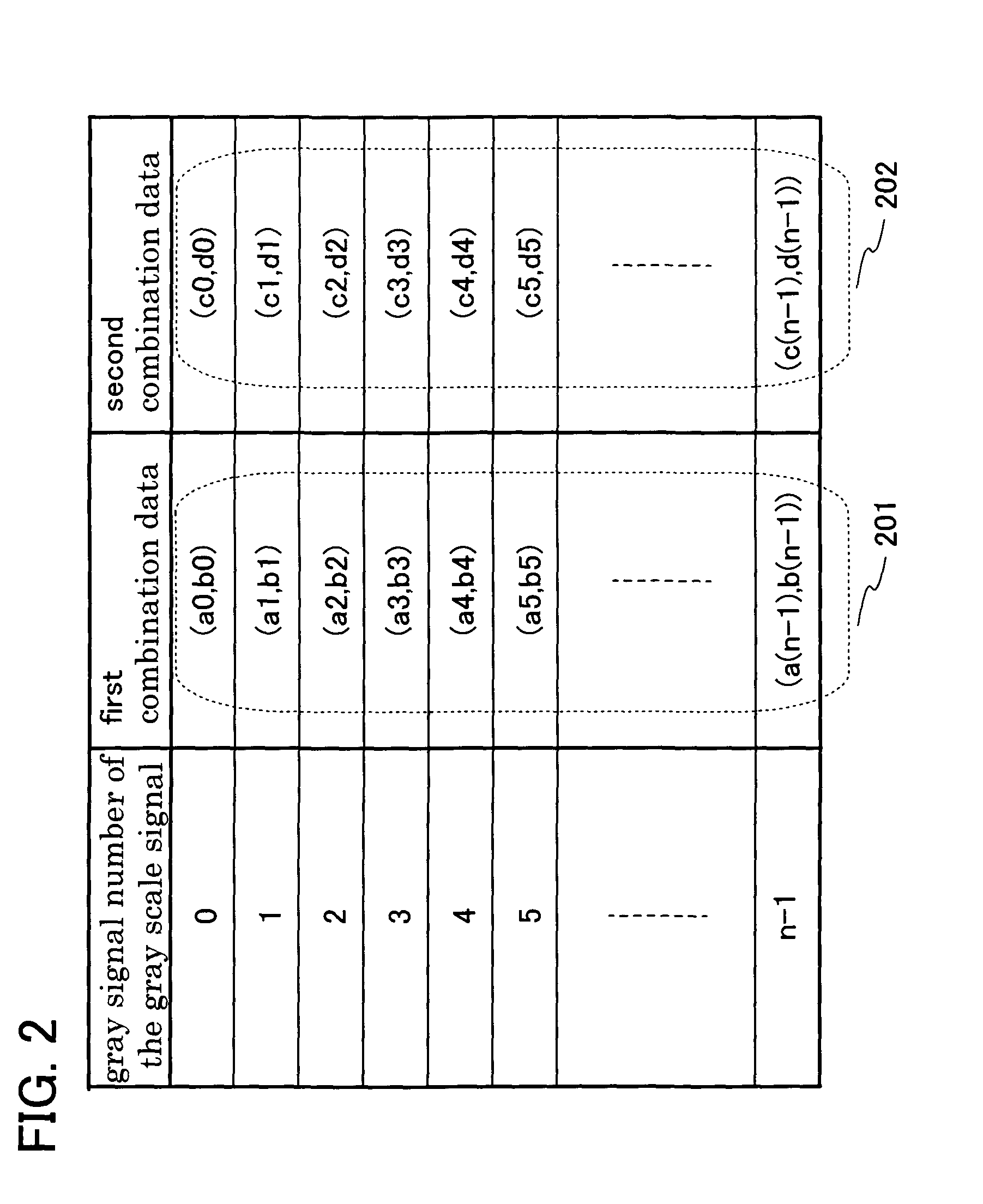
[0280]During the first period and the second period described in FIG. 5 in Embodiment Mode 1, any one combination data in the LUT is referred to and the sub-grayscale signal generated in the grayscale data conversion portion is output to each sub-pixel. Even if display is performed with the same level of grayscale, by generating the sub-grayscale signal in the grayscale data conversion portion to perform display of the display portion, the liquid crystal molecules are made slanted in different directions every desired period to increase directions of alignment, so that the viewing characteristics of a viewer can be improved.

[0281]As shown in FIG. 14A, the first period and the second period of the present invention described in...


PUM


Abstract

To provide a liquid crystal display device which can improve viewing angle characteristics and a driving method of the liquid crystal display device, and an electronic device including the liquid crystal display device. In a liquid crystal display device which performs display by aligning liquid crystal molecules at a tilt or radially at a tilt, one pixel is divided into a plurality of regions (sub-pixels) and a signal applied to each sub-pixel is made different every desired period. Alternatively, a signal applied to each sub-pixel is made different with respect to an adjacent pixel. To improve viewing angle characteristics by changing transmittance of the liquid crystal molecules every desired period in addition to improving the viewing angle characteristics of a viewer by making the liquid crystal molecules slanted to increase directions of alignment.

Description

BACKGROUND OF THE INVENTION[0001]1. Field of the Invention[0002]The present invention relates to an object, a method, or a method for manufacturing the object. Specifically, the present invention relates to a display device or a semiconductor device. Further, the present invention relates to a liquid crystal display device. Alternatively, the present invention relates to a driving method of a liquid crystal display device. Alternatively, the present invention relates to an electronic device provided with a display device.[0003]2. Description of the Related Art[0004]A liquid crystal display device is used for various electronic products such as a mobile phone, a television receiver, and the like. Since a liquid crystal display device is still required to be improved in contrast ratio, responsiveness (hereinafter referred to as quick responsiveness) of liquid crystal molecules for input signals, and viewing angle characteristics, research on higher image quality is significantly activ...

Claims


Application Information

Patent Timeline
IPC IPC(8): G09G3/36
CPCG09G3/2074G09G3/3685G09G2320/028G09G2300/0465G09G2300/0443
Inventor KIMURA, HAJIME
Owner SEMICON ENERGY LAB CO LTD
Why Eureka
Try Eureka