Liquid crystal television and liquid crystal display apparatus

a technology of liquid crystal display and liquid crystal television, which is applied in the direction of television systems, electrical apparatus casings/cabinets/drawers, instruments, etc., can solve the problems of rising inner temperature of pdp, inability to project liquid crystal display apparatus from the wall, and inability to meet the needs of the user, so as to reduce the distance between the wall and the display face of the liquid crystal display apparatus, the effect of reducing the width of the heat radiating spa

Inactive Publication Date: 2006-10-05
FUNAI ELECTRIC CO LTD
View PDF13 Cites 10 Cited by
  • Summary
  • Abstract
  • Description
  • Claims
  • Application Information

AI Technical Summary

Benefits of technology

[0021] According to the liquid crystal television according to the first aspect of the invention, as described above, a heat radiating space can be formed between the back face of the cabinet of the liquid crystal television and the wall in hanging on the wall by bringing the front end side of the pivoting member into contact with the wall to form the predetermined gap between the wall and the back face of the cabinet by inclining the pivoting member of the stand member by the predetermined angle to the side of the wall in the closed state of being contained in the liquid crystal television in hanging on the wall. Thereby, different from a case of bringing the wall and the back face of the liquid crystal television into close contact with each other without a gap therebetween, heat can excellently be radiated from the heat radiating hole provided at the back face of the liquid crystal television to outside. As a result, also in hanging on the wall, the inner temperature of the liquid crystal television can effectively be restrained from rising. Further, when the angle of inclining the stand member to the side of the wall is reduced, a width of the heat radiating space can be reduced. Thereby, a distance between the wall and a display face of the liquid crystal television can be reduced and therefore, in hanging on the wall, a distance of projecting the liquid crystal television from the wall can be reduced. Further, by providing the projected piece for restricting the pivoting member to the position of being inclined by the predetermined angle to the side of the wall in the closed state in hanging on the wall, by the projected piece, the pivoting member can be inclined by the predetermined angle to the side of the wall easily in the closed state in hanging on the wall. Further, by integrally providing the projected piece to the base member and providing a pair of left and right thereof, the projected piece can be provided without increasing a number of parts and by the pair of projected pieces, in comparison with a case of the single projected piece, a position of an inclined angle in the closed state of the pivoting member can solidly be maintained.
[0023] According to the liquid crystal display apparatus according to the second aspect of the invention, as described above, a heat radiating space can be formed between the back face of the cabinet of the liquid crystal television 10 and the wall in hanging on the wall by bringing the front end side of the pivoting member into contact with the wall to form the predetermined gap between the wall and the back face of the cabinet by inclining the pivoting member of the stand member by the predetermined angle to the side of the wall in the closed state of being contained in the liquid crystal display apparatus in hanging on the wall. Thereby, different from a case of bringing the wall and the back face of the liquid crystal apparatus into close contact with each other without a gap therebetween, heat can excellently be radiated from the heat radiating hole provided at the back face of the liquid crystal display apparatus to outside. As a result, also in hanging on the wall, an inner temperature of the liquid crystal display apparatus can effectively be restrained from rising. Further, when an angle of inclining the stand member to the side of the wall is reduced, a width of the heat radiating space can be reduced. Thereby, a distance between the wall and a display face of the liquid crystal display apparatus can be reduced and therefore, in hanging on the wall, a distance of projecting the liquid crystal display apparatus from the wall can be reduced.
[0024] According to the liquid crystal display apparatus according to the second aspect, preferably, the base member of the stand member is provided with a projected piece for restricting the pivoting member to a position of being inclined by the predetermined angle to the side of the wall in the closed state in hanging on the wall. When constituted in this way, by the projected piece, the pivoting member can be inclined by the predetermined angle to the side of the wall 30 easily in the closed state in hanging on the wall.
[0025] In the liquid crystal display apparatus provided with the projected piece at the base member of the stand member, preferably, the projected piece is integrally provided with the base member and a pair of left and right thereof are provided. When constituted in this way, the projected piece can be provided without increasing a number of parts, and by the pair of projected pieces, in comparison with a case of the single projected piece, a position of the inclined angle in the closed state of the pivoting member can further solidly be maintained.
[0026] In the liquid crystal display apparatus according to the second aspect, preferably, the front end side of the pivoting member of the stand member is provided with a contact portion made of rubber brought into contact with a wall face in hanging on the wall. When constituted in this way, in hanging on the wall, by bringing the contact portion made of rubber having an elasticity into contact with the wall in a face-like shape, the wall can be restrained from being damaged.

Problems solved by technology

Thereby, in hanging on the wall, heat cannot be radiated from the heat radiating hole 102b to outside and therefore, there poses a problem that an inner temperature of the liquid crystal television 110 rises.
Further, when the heat radiating hole is provided at the back face of the cabinet, the heat radiating hole is closed by the wall and therefore, it seems that there poses a problem that the inner temperature of the liquid crystal television rises.
Further, when the heat radiating hole is provided at the back face of the cabinet, the heat radiating hole is closed by the wall and therefore, it seems that the problem that the inner temperature of PDP rises is posed.
Further, when the heat radiating hole is provided at the back face of the cabinet, the heat radiating hole is closed by the wall and therefore, it seems that the problem that the inner temperature of the display apparatus rises is posed.

Method used


Image

  • Liquid crystal television and liquid crystal display apparatus
  • Liquid crystal television and liquid crystal display apparatus
  • Liquid crystal television and liquid crystal display apparatus

Examples


Embodiment Construction

[0046] The embodiment of the invention will be explained in reference to the drawings as follows. Further, in the following embodiment, en explanation will be given by taking an example of a liquid crystal television as an example of a liquid crystal display apparatus.

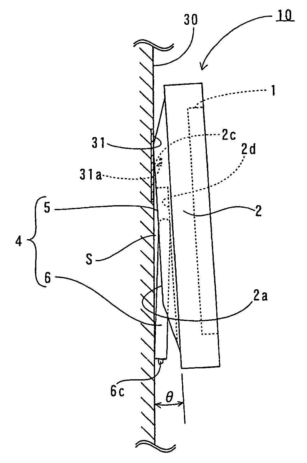
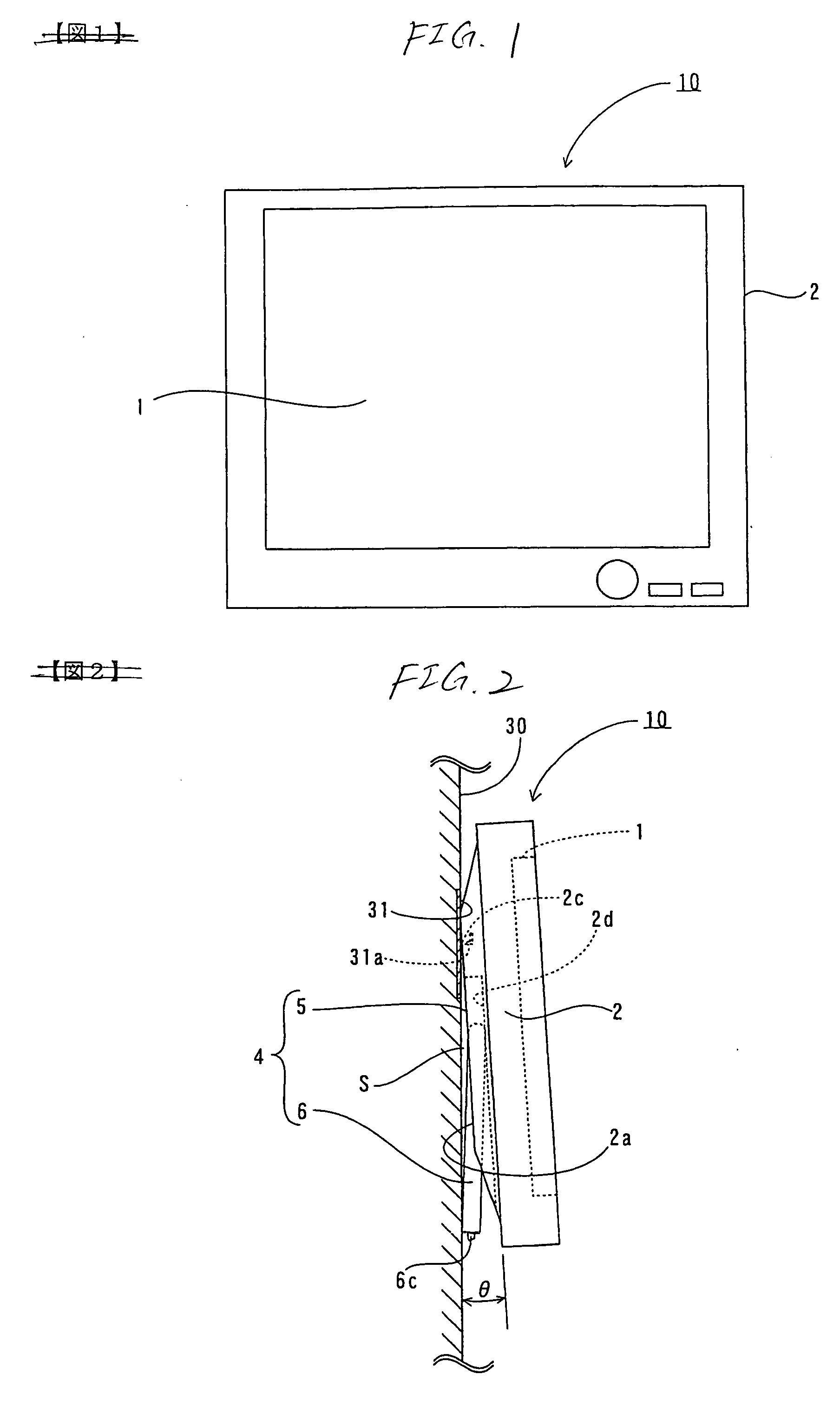
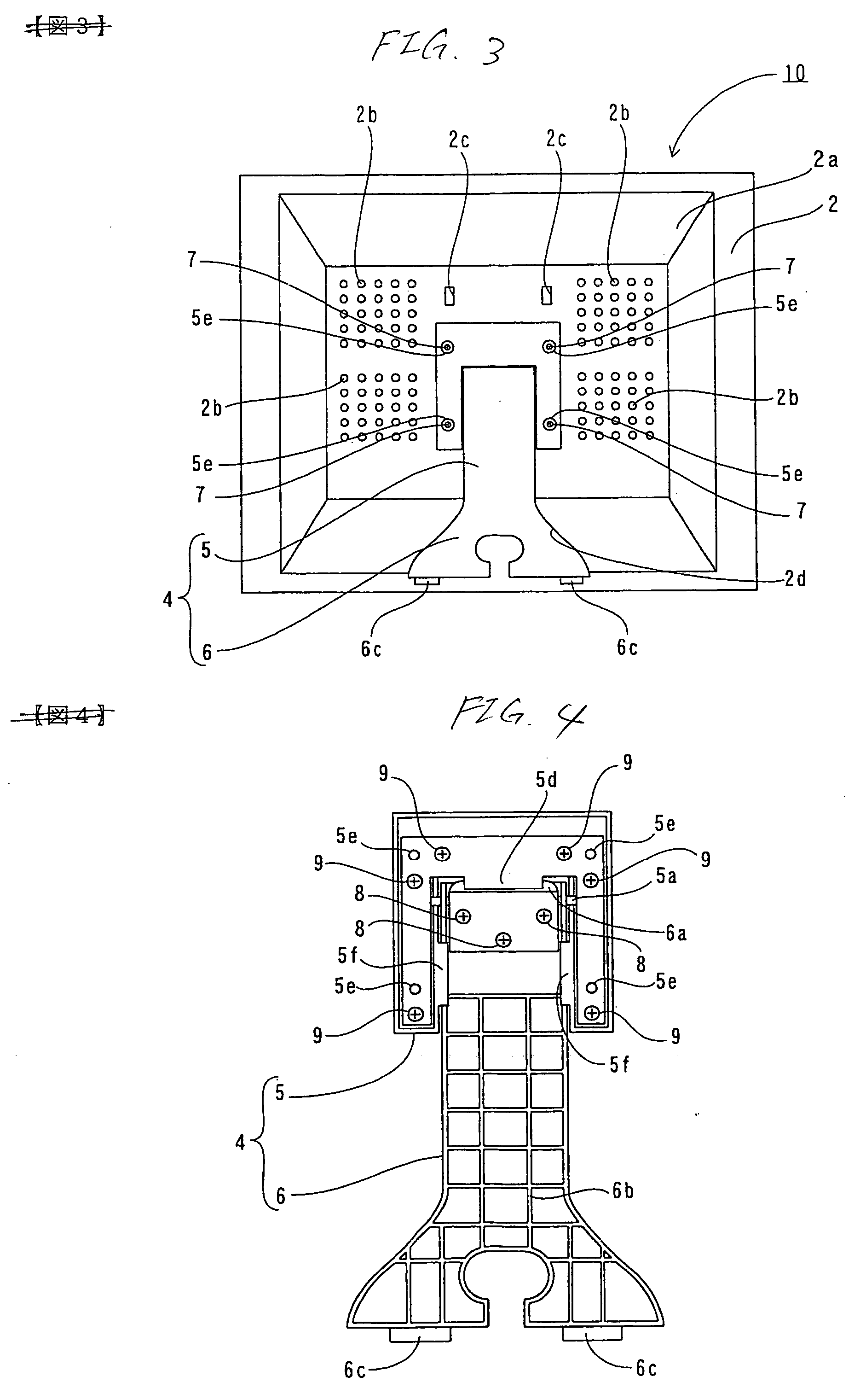
[0047]FIG. 1 is a front view showing a total constitution of a liquid crystal television according to an embodiment of the invention. FIG. 2 is a side view showing a state of attaching the liquid crystal television according to the embodiment shown in FIG. 1 to an attaching plate of a wall. FIG. 3 through FIG. 9 are views for explaining details of a structure of the liquid crystal television according to the embodiment shown in FIG. 1. First, a structure of a liquid crystal television 10 according to the embodiment of the invention will be explained in reference to FIG. 1 through FIG. 9.

[0048] As shown by FIG. 1 through FIG. 3, the liquid crystal television 10 according to the embodiment of the invention is provided ...


PUM


Abstract

A liquid crystal display apparatus includes: a cabinet constituting an apparatus main body; a stand member including: a base member attached to be contained in a recess portion of a back face of the cabinet; and a pivoting member attached to the base member; an engaging portion provided at the back face and engaged with a side of a wall in hanging on the wall; and a heat radiating hole provided at the back face, wherein: the stand member supports the apparatus main body by bringing the pivoting member into an opened state, and contains the pivoting member in the back face in mounting on the wall; the pivoting member is brought into contact with the wall at a front end side of the pivoting member to form a predetermined gap between the wall and the back face in hanging on the wall.

Description

BACKGROUND OF THE INVENTION [0001] 1. Field of the Invention [0002] The invention relates to a liquid crystal television and a liquid crystal display apparatus, particularly relates to a liquid crystal television and a liquid crystal display apparatus including a heat radiating hole and a stand member provided on a back face of a cabinet. [0003] 2. Description of the Related Art [0004] In a background art, as an example of a liquid crystal display apparatus, a liquid crystal television is known. FIG. 12 is a rear view showing a total constitution of a liquid crystal television according to an example of a background art. FIG. 13 is a side view in mounting the liquid crystal television according to the example of the background art shown in FIG. 12. FIG. 14 through FIG. 16 are views showing details of a structure of the liquid crystal television according to the example of the background art shown in FIG. 12. First, a structure of a liquid crystal television 110 according to an examp...

Claims


Application Information

Patent Timeline
Patent Type & Authority Applications(United States)
IPC IPC(8): H04N5/64
CPCH04N5/64Y10S248/917Y10S248/921
Inventor OGAWA, MASUOISHII, HIROKI
Owner FUNAI ELECTRIC CO LTD
Why Eureka
Try Eureka