Failure-monitoring program and load-balancing device

a failure monitoring and load-balancing technology, applied in multi-programming arrangements, instruments, data switching networks, etc., can solve problems such as failure in a server to which packets are to be delivered, and failure of the server located behind the destination server

Inactive Publication Date: 2006-10-05
FUJITSU LTD
View PDF3 Cites 27 Cited by
  • Summary
  • Abstract
  • Description
  • Claims
  • Application Information

AI Technical Summary

Benefits of technology

[0015] In order to accomplish the above object, a failure-monitoring method for monitoring destination servers for failure in order to deliver request packets from clients to the destination servers and balance loads imposed on the destination servers is provided. The failure-monitoring method comprises: the steps of: (a) generating and storing for each of the destination servers definition-for-monitoring information in which one or more servers to be monitored, a monitoring procedure including a definition of a monitoring packet used in diagnosis of the one or more servers to be monitored, and, when necessary, a criterion for determining normality of the one or more servers to be monitored are defined; (b) transmitting the monitoring packet defined in the monitoring procedure to each of the one or more servers to be monitored, in accordance with the definition-for-monitoring information; and (c) determining that the server to be monitored is faulty and delivery of one or more request packets to one of the destination servers corresponding to the server to be monitored is not allowed, when no response is returned from the server to be monitored, or when a response packet received from the server to be monitored does not satisfy the criterion.
[0016] In addition, in order to accomplish the aforementioned object, a load-balancing device for delivering request packets from clients to destination servers so as to balance loads imposed on the destination servers, and monitoring the destination servers for failure is provided. The load-balancing device comprises: a definition-management unit which generates destination information in which the destination servers are defined as servers to which the request packets from the clients are to be delivered, generates definition-for-monitoring information for each of the destination servers, and manages the destination information and the definition-for-monitoring information, where one or more servers to be monitored, a monitoring procedure including a definition of a monitoring packet used in diagnosis of the one or more servers to be monitored, and, when necessary, a criterion for determining normality of the one or more servers to be monitored are defined in the definition-for-monitoring information; a failure-monitoring unit which transmits the monitoring packet defined in the monitoring procedure to each of the one or more servers to be monitored, in accordance with the definition-for-monitoring information, determines that each of the one or more servers to be monitored is faulty and delivery of one or more request packets to one of the destination servers corresponding to the server to be monitored is not allowed, when no response is returned from the server to be monitored, or when a response packet received from the server to be monitored does not satisfy the criterion, and determines that delivery of one or more request packets to one of the destination servers corresponding to each of the one or more servers to be monitored is allowed when the response packet received from the server to be monitored satisfies the criterion; and a delivery unit which delivers a request packet from a client to one of the destination servers to which delivery of one or more request packets is determined to be allowed, when the request packet is received from the client.

Problems solved by technology

However, according to the conventional techniques for monitoring a load-balancing system for failure, it is difficult to monitor for failure a server located behind a server to which packets are to be delivered.
In particular, according to the conventional techniques, failure in a server to which packets are to be delivered is determined on the basis of only whether or not a response to a monitoring packet transmitted from the load-balancing device is returned.
As explained above, since, according to the conventional failure-monitoring techniques, the monitoring packets are exchanged only between the load-balancing device and the destination servers, it is impossible to monitor for failure the servers located behind the destination servers.

Method used


Image

  • Failure-monitoring program and load-balancing device
  • Failure-monitoring program and load-balancing device
  • Failure-monitoring program and load-balancing device

Examples


Embodiment Construction

[0035] The embodiment of the present invention is explained below with reference to drawings.

Outline of the Present Invention

[0036] First, an outline of the present invention which is realized in the embodiment is indicated, and thereafter details of the embodiment are explained.

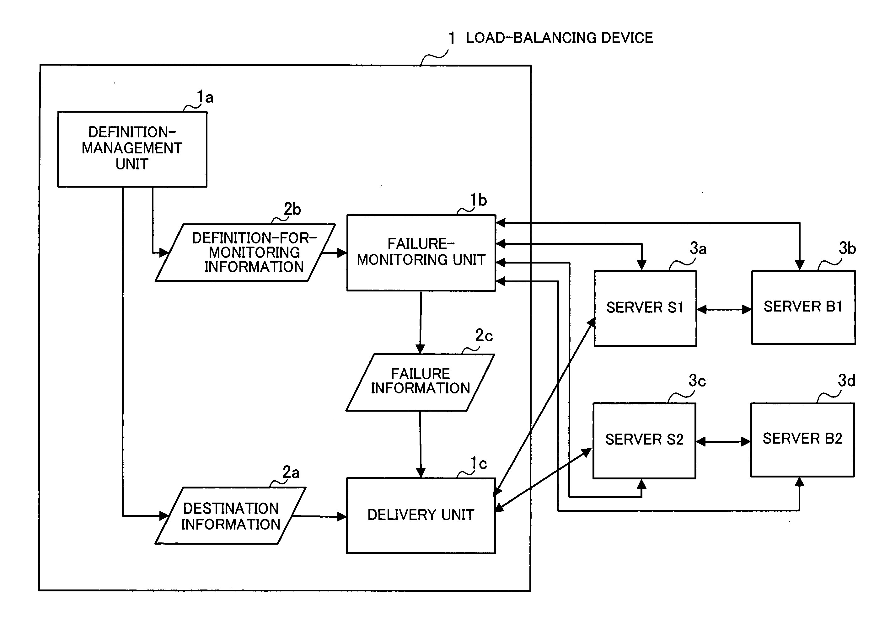
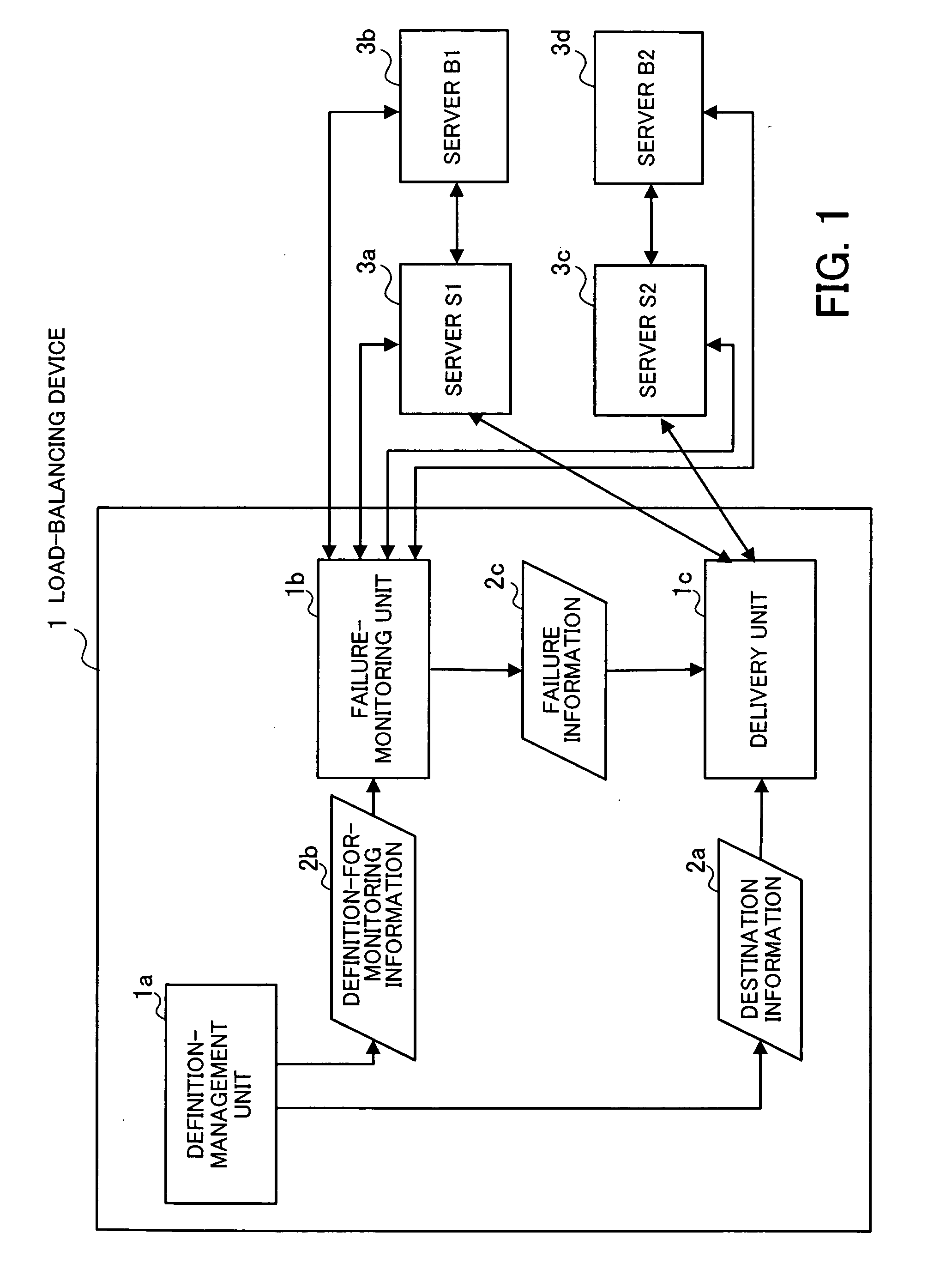
[0037]FIG. 1 is a conceptual diagram illustrating the present invention which is realized in the embodiment. The load-balancing device 1 according to the present invention comprises a definition-management unit 1a, a failure-monitoring unit 1b, and a delivery unit 1c. When request packets from clients (not shown) are inputted into the load-balancing device 1, the load-balancing device 1 distributes the request packets among servers so as to balance the load imposed on the servers.

[0038] In the configuration of FIG. 1, the combination of the server S1 (3a) and the server B1 (3b) realizes a predetermined processing function, i.e., the server S1 (3a) and the server B1 (3b) cooperate to realize the predeter...


PUM


Abstract

In a method for monitoring servers including destination servers for failure: definition-for-monitoring information including servers to be monitored, a monitoring procedure including a definition of a monitoring packet used in diagnosis of the servers to be monitored, and a criterion for determining normality of the servers to be monitored is generated and stored for each destination server; the monitoring packet is transmitted to each server to be monitored, in accordance with the definition-for-monitoring information; and it is determined that the server to be monitored is faulty and delivery of request packets to one of the destination servers corresponding to the server to be monitored is not allowed, when no response is returned from the server to be monitored, or when a response packet received from the server to be monitored does not satisfy the criterion.

Description

CROSS-REFERENCE TO RELATED APPLICATIONS [0001] This application is based upon and claims the benefits of priority from the prior Japanese Patent Application No. 2005-101161, filed on Mar. 31, 2005, the entire contents of which are incorporated herein by reference. BACKGROUND OF THE INVENTION [0002] 1) Field of the Invention [0003] The present invention relates to a failure-monitoring program and a load-balancing device for monitoring servers for a failure, and balancing load imposed on servers by distributing request packets from clients among the servers. [0004] 2) Description of the Related Art [0005] In recent years, in order to ensure data processing capacity of servers and prevent lowering of responsibility caused by access concentration in the network systems having increasing variety and complexity, the load-balancing technology has become essential. [0006]FIG. 17 is a diagram illustrating an example of a conventional load-balancing system. In the load-balancing system of FIG...

Claims


Application Information

Patent Timeline
Patent Type & Authority Applications(United States)
IPC IPC(8): H04J1/16G06F9/50G06F13/00G06F15/00H04L12/70
CPCH04L12/2602H04L41/06H04L43/10H04L43/00H04L41/069
Inventor MATSUMOTO, TSUYOSHI
Owner FUJITSU LTD
Why Eureka
Try Eureka