
Multi-axial laminate composite structures and methods of forming the same

a composite structure and multi-axial technology, applied in the field of composite structures, can solve the problems of limiting the operating stresses of the structure, adding a significant amount of weight to the structure,

Inactive Publication Date: 2006-10-05
THE BOEING CO
View PDF91 Cites 81 Cited by
  • Summary
  • Abstract
  • Description
  • Claims
  • Application Information

AI Technical Summary

Problems solved by technology

Fiber reinforced composite structures formed in the foregoing manner (i.e. having a 0 / ±45 / 90 degree layer configuration) may exhibit insufficient strength unless a significant number of layers are used, which generally adds a significant amount of weight to the structure.
Moreover, the foregoing orientations (e.g. 0 / ±45 / 90) in the composite structure generally include seams and potential areas of weakness, which may allow cracks to propagate through the structure, thus limiting the permissible operating stresses of the structure.

Method used


Image

  • Multi-axial laminate composite structures and methods of forming the same
  • Multi-axial laminate composite structures and methods of forming the same
  • Multi-axial laminate composite structures and methods of forming the same

Examples


Embodiment Construction

[0014] The present invention relates to multi-axial laminate composite structures. Many specific details of certain embodiments of the invention are set forth in the following description and in FIGS. 1 through 5 to provide a thorough understanding of such embodiments. One skilled in the art, however, will understand that the present invention may have additional embodiments, or that the present invention may be practiced without several of the details described in the following description.

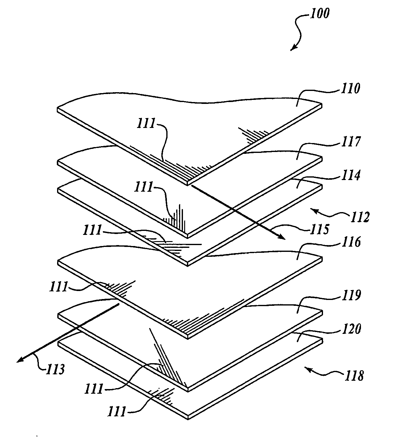
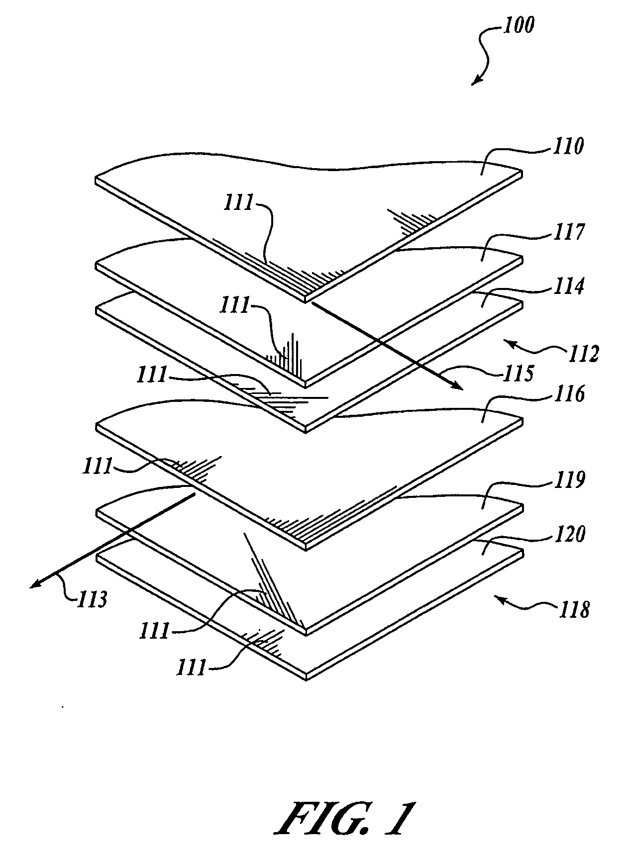
[0015]FIG. 1 is a partial exploded isometric view of a multi-axial composite laminate structure 100 according to an embodiment of the invention. The multi-axial composite laminate structure 100 includes a first unidirectional layer 116 and a second unidirectional layer 110. The first unidirectional layer 116 includes a plurality of reinforcement fibers 111 that are approximately parallel and aligned with a first selected direction 113. The second unidirectional layer 110 also includes a pluralit...


PUM

PropertyMeasurementUnit
Fractionaaaaaaaaaa
Fractionaaaaaaaaaa
Angleaaaaaaaaaa

Abstract

Composite laminate structures and methods of forming the same are disclosed. In one embodiment, the structure includes a first bidirectional layer having a first portion that includes parallel reinforcement fibers oriented at a first angle relative to a first direction and a second portion that includes parallel reinforcement fibers oriented at a second angle relative to the first direction. The structure further includes a second bidirectional layer having a first portion that includes parallel reinforcement fibers oriented at a third angle relative to the first direction and a second portion that includes parallel reinforcement fibers oriented at a fourth angle relative to the first direction. At least one unidirectional layer having a plurality of parallel reinforcement fibers is coupled to at least one of the first bidirectional layer and the second bidirectional layer.

Description

CROSS REFERENCE TO RELATED APPLICATIONS [0001] This patent application is related to the following co-pending, commonly-owned U.S. patent applications, which applications are hereby incorporated by reference: U.S. patent application Ser. No. (to be determined) entitled “Composite Structural Member Having An Undulating Web and Method of Forming the Same”, filed under Attorney Docket No. BING-1-1133; U.S. patent application Ser. No. (to be determined) entitled “Hybrid Fiberglass Composite Structures and Methods of Forming the Same” filed under Attorney Docket No. BING-1-1149; and U.S. patent Ser. No. (to be determined) entitled “Composite Structural Member and Method for Forming the Same” filed under Attorney Docket No. BING-1-1151.FIELD OF THE INVENTION [0002] This invention relates generally to composite structures and, more specifically, to multi-axial laminate composite structures. BACKGROUND OF THE INVENTION [0003] Fiber reinforced laminate composites are widely used in weight se...

Claims


Application Information

Patent Timeline
IPC IPC(8): B64C1/00B32B27/04
CPCB29C70/083B29C70/202B29C70/207B29C70/226Y02T50/433B29C70/24B29L2031/3076B29L2031/3082B29L2031/3085B29C70/228Y02T50/40Y10T428/24994
Inventor KISMARTON, MAX U.
Owner THE BOEING CO
Learn More