Vibration-absorbing weight system for golf club head
a golf club head and weight system technology, applied in the field of golf club head vibration-absorbing weight system, can solve the problems of unsatisfactory vibration-absorbing effect, adversely affecting the striking effect, and significantly affecting the overall striking effect, and achieve the effect of simplifying the assembly of the weight member
- Summary
- Abstract
- Description
- Claims
- Application Information
AI Technical Summary
Benefits of technology
Problems solved by technology
Method used
Image
Examples
first embodiment
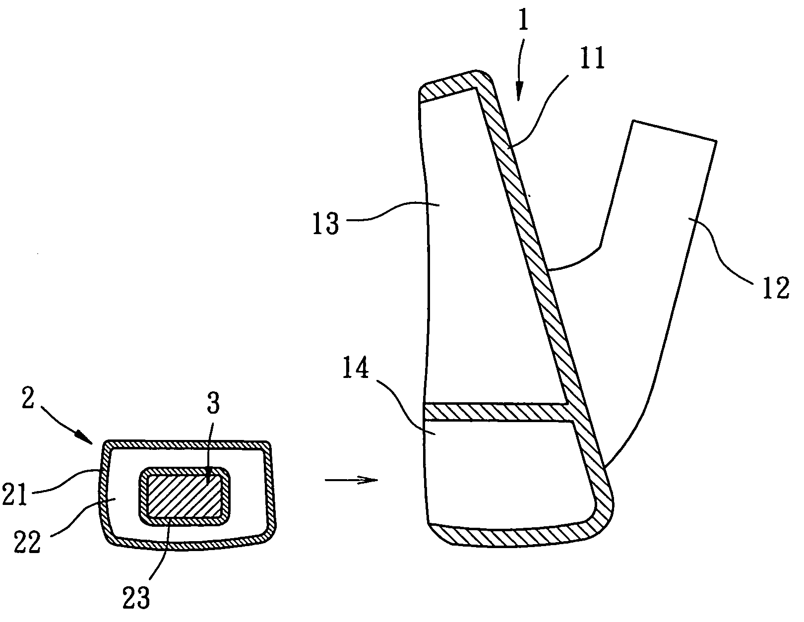
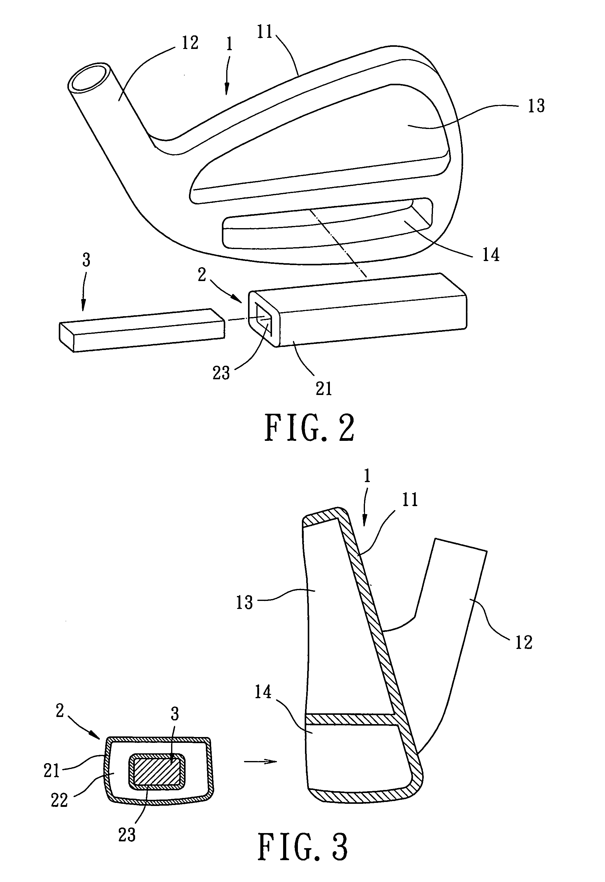
[0039] Referring to FIG. 2 through 4, a golf club head in accordance with the present invention comprises a body 1, at least one gas cushion 2 (only one in this embodiment), and at least one weight member 3 (only one in this embodiment). The body 1 is a body for an iron club head. The body 1 includes a striking plate 11, a hosel 12, a back cavity 13, and a compartment 14 that provides a vibration-absorbing area. The striking plate 11 can be mounted to the body 1 by welding, brazing, insertion, or screwing. The striking plate 11 has a front side for striking golf balls. Alternatively, the body 1 and the striking plate 11 can be integrally formed with each other, with the striking plate 11 providing a striking face of the body 1 for striking golf balls.
[0040] The back cavity 13 is defined in a rear side of the body 1. The rear side of the body 1 is thus exposed to provide a space for rearward deformation of the striking plate 11. The compartment 14 is defined in a bottom or lower port...
second embodiment
[0050]FIG. 5 illustrates the invention, wherein the body 1 of the golf club head includes two compartments 14a and 14b each for receiving a gas cushion 2 / weight member 3. In the illustrated embodiment, the compartments 14a and 14b are defined in the heel and the toe of the rear side of the body 1 that are respectively adjacent to and proximal to the hosel 12. Since the compartments 14a and 14b are located in an area where the residual vibrations concentrate and since the gas cushions 2 are in intimate contact with the rear side of the striking plate 11, a vibration-absorbing effect is provided while allowing adjustment of the center of gravity as well as improvement (or adjustment) of the inertia moment and the striking effect. Thus, the residual vibrations after striking a golf ball with the golf club head can be effectively absorbed without reducing the momentum. The gripping comfort of the golf club head and the direction controllability and striking accuracy of the golf ball are...
third embodiment
[0051]FIG. 6 illustrates the invention, wherein the body 1 is of wooden club type and includes a striking plate 11, a hosel 12, and at least one compartment 14 (only one in this embodiment). The compartment 14 is defined in a sealed interior space 15 of the body 1 and adjacent to the striking plate 11. At least one gas cushion 2 (only one in this embodiment) and at least one weight member 3 (only one in this embodiment) are mounted in the compartment 14. The gas cushion 2 includes a bladder 21 defining a gas chamber 22 and an engaging section 23. Further, the gas cushion 2 includes a slit 231 through which a receiving space defined by the engaging section 23 is in communication with outside. The weight is inserted into the receiving space defined by the engaging section 23 via the slit 231, and the gas cushion 2 / weight member 3 is then inserted into the compartment 14 of the body 1. The gas cushion 2 / weight member 3 allows adjustment of the center of gravity to improve (or adjust) t...
PUM
 Abstract
Description
Claims
Application Information
 - R&D
- Intellectual Property
- Life Sciences
- Materials
- Tech Scout
- Unparalleled Data Quality
- Higher Quality Content
- 60% Fewer Hallucinations
Browse by: Latest US Patents, China's latest patents, Technical Efficacy Thesaurus, Application Domain, Technology Topic, Popular Technical Reports.
© 2025 PatSnap. All rights reserved.Legal|Privacy policy|Modern Slavery Act Transparency Statement|Sitemap|About US| Contact US: help@patsnap.com


