Process for determining the operating parameters of an injection device

Active Publication Date: 2006-10-05
DELPHI TECH IP LTD
View PDF3 Cites 14 Cited by
  • Summary
  • Abstract
  • Description
  • Claims
  • Application Information

AI Technical Summary

Benefits of technology

[0010] The present invention has the aim of proposing a process for determining the operating parameters of an injection device of a combustion engine which avoids at least certain of the above-mentioned disadvantages and which is more accura

Problems solved by technology

When the pressure inside the control chamber drops to a certain point, the force applied to the needle due to the pressure inside the control chamber is no longer sufficient to keep the needle in its closed position.
In addition, mechanical wear can also affect the accuracy of the quantity of fuel injected.
However, this solution is sensitive to vibrations and this causes accuracy pro

Method used


Image

  • Process for determining the operating parameters of an injection device
  • Process for determining the operating parameters of an injection device
  • Process for determining the operating parameters of an injection device

Examples


Embodiment Construction

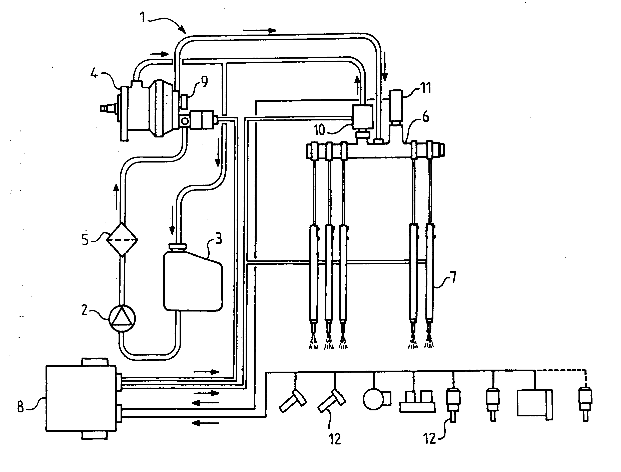
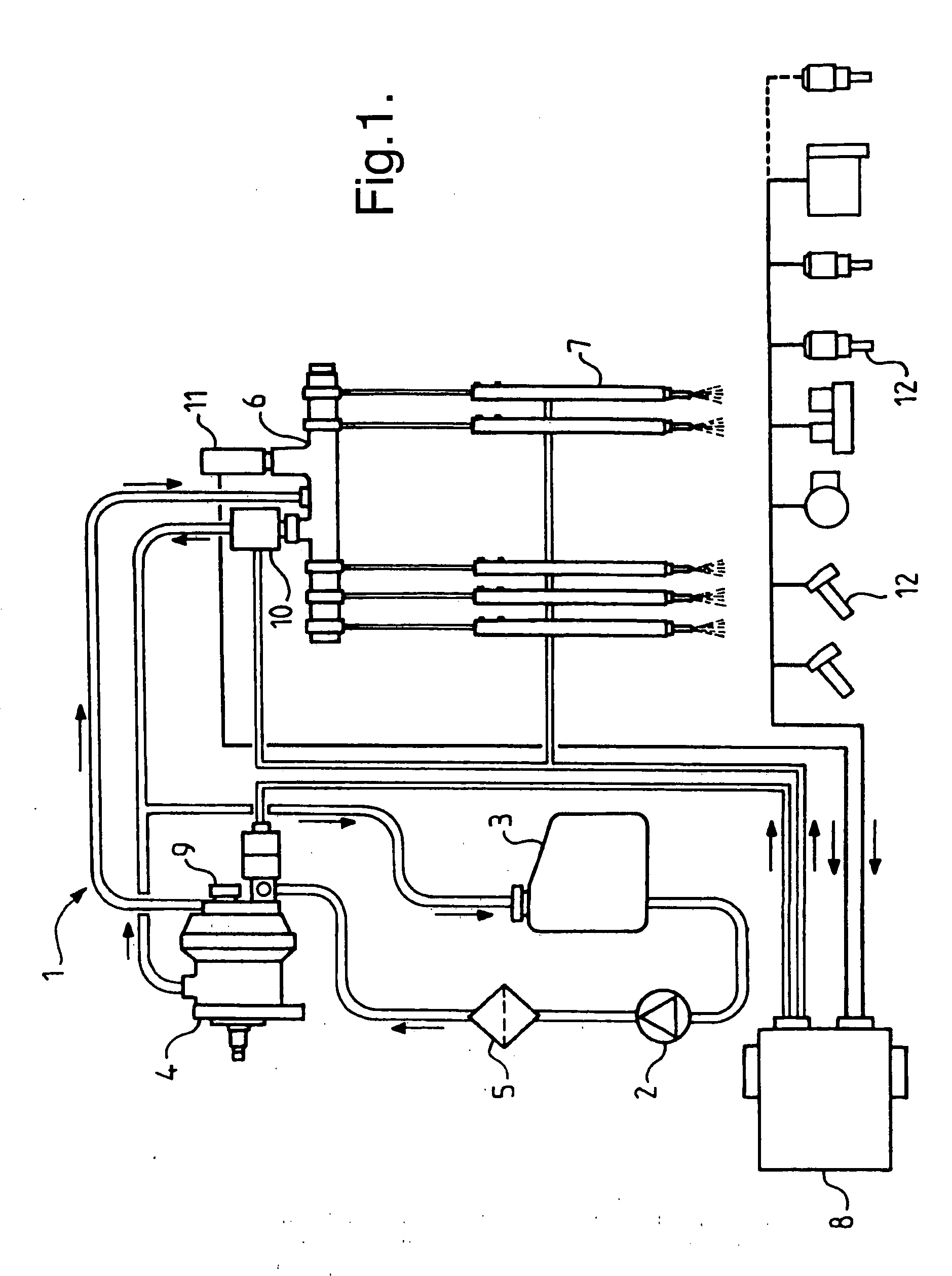
[0049] With reference to FIG. 1, this shows a fuel supply system 1 for an internal combustion engine. The supply system 1 is arranged in a vehicle (not shown) and co-operates with an engine (not shown), the injectors 7 injecting fuel into cylinders (not shown) of the engine, for example diesel. The supply system 1 includes a low pressure pump 2, also called the lift pump, the delivery pressure of which is for example approximately equal to 6 bars. The pump 2 is so arranged as to be able to remove fuel from a fuel tank 3 and supply fuel to an intake of a high pressure pump 4 via a filter 5. The delivery pressure of the pump 4 is adjustable within a range of the order of 200-1800 bars or higher. The high pressure pump 4 is arranged to load a common rail 6 with fuel at high pressure. Injectors 7 are connected to the common rail 6, each of the injectors 7 being controlled to open and close by an electronic control unit 8, currently called the drive computer, by means of control signals....


PUM


Abstract

A process for determining the operating parameters of an injection device of a combustion engine includes the steps of: (a) selecting an injector to test; (b) calculating a mean velocity associated with a preceding injector arranged before the injector to test; c) applying to the injector to test an injection control signal including at least one test pulse having an adjustable parameter; (d) calculating a mean velocity associated with the injector to test; (e) calculating a difference between the mean velocity calculated in step d) and the mean velocity calculated in step b); (f) repeating steps b) to d) for at least another engine cycle, each time varying the parameter of the test pulse; (g) determining a value of the parameter of the test pulse for which the mean velocity difference exceeds a predetermined threshold; and storing the parameter value.

Description

TECHNICAL FIELD [0001] The present invention has as its object a process for determining the operating parameters, also called a learning process, of an injection device of a combustion engine. BACKGROUND OF THE INVENTION [0002] Conventionally, an injection device includes a plurality of injectors, each of the injectors being controlled to open and close by an electronic control means, by means of control signals permitting driving of one or more pilot injections and a main injection at each of the injectors. The injectors used may be of several types, for example of solenoid type or piezoelectric type. [0003] The document EP 0 740 068 describes a solenoid injector. The injector includes an injector body. At its lower end, the injector body defines a seat in which the lower end of a needle is able to engage, the needle being able to slide between an open position in which it permits ejection of fuel from the injector and a closed position in which it sealedly closes the injector. Th...

Claims


Application Information

Patent Timeline
IPC IPC(8): F02M65/00
CPCF02D41/123F02D41/1497F02D41/403F02D41/2441F02D41/247F02D41/2438
Inventor COCHET, THIERRYMEISSONNIER, GUILLAUME
Owner DELPHI TECH IP LTD
Why Eureka
Try Eureka