Joint driving device

a driving device and joint technology, applied in the direction of mechanical control devices, instruments, prostheses, etc., can solve the problems of reduced control accuracy, inability to perform operations, configuration is not capable of generating variable torques with a certain translational force, etc., to achieve flexible and continuous switching, higher outputs, and higher reliability

Active Publication Date: 2009-07-07
PANASONIC CORP
View PDF5 Cites 14 Cited by
  • Summary
  • Abstract
  • Description
  • Claims
  • Application Information

AI Technical Summary

Benefits of technology

[0026]According to the present invention, there is provided the securing-position variable mechanism to enable controlling the interval between the elastic body actuators, which enables flexibly and continuously switching between the operation which prioritizes the rotational torque and the operation which prioritize the rotational displacement, depending on the situation. Accordingly, when the robot arm is constituted by the joint driving device according to the present invention, it is possible to realize the robot arm with higher reliability capable of flexibly varying the characteristics such as generating higher outputs or increasing the operable range depending on the situation as follows. For example, it is possible to realize a robot arm capable of generating a greater torque for griping and capable of carrying an object with a greater weight and also capable of providing a greater movable range of the joint for providing a greater operable range.

Problems solved by technology

However, the aforementioned configuration of Patent Document 1 may induce looseness of wires and fall from the pulleys, which may reduce the control accuracy or may make it impossible to perform operations.
Therefore, when the aforementioned configuration is applied to a robot and the like, the configuration is not capable of generating variable torques with a certain translational force depending on the situation, such as situations which require a greater force for griping an object with a greater weight and situations which require a greater operable range for operating the robot over a wider range.

Method used


Image

  • Joint driving device
  • Joint driving device
  • Joint driving device

Examples


first embodiment

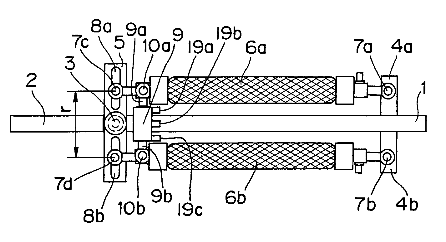
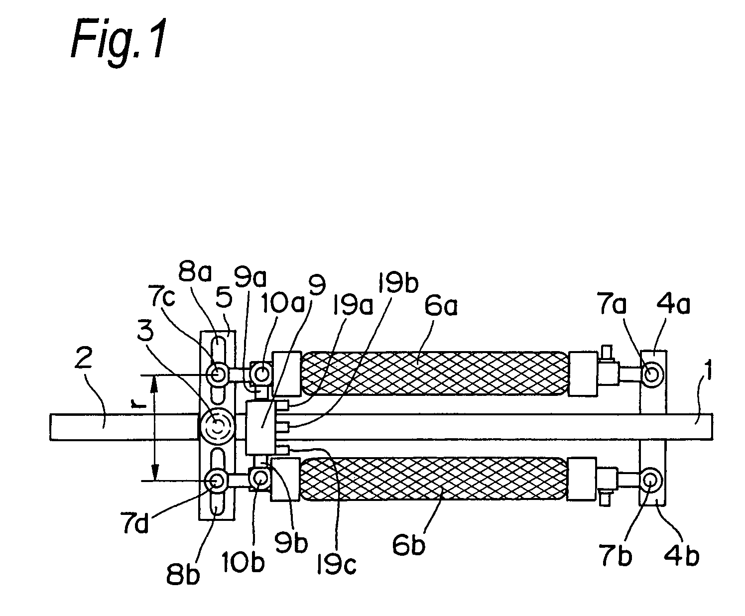
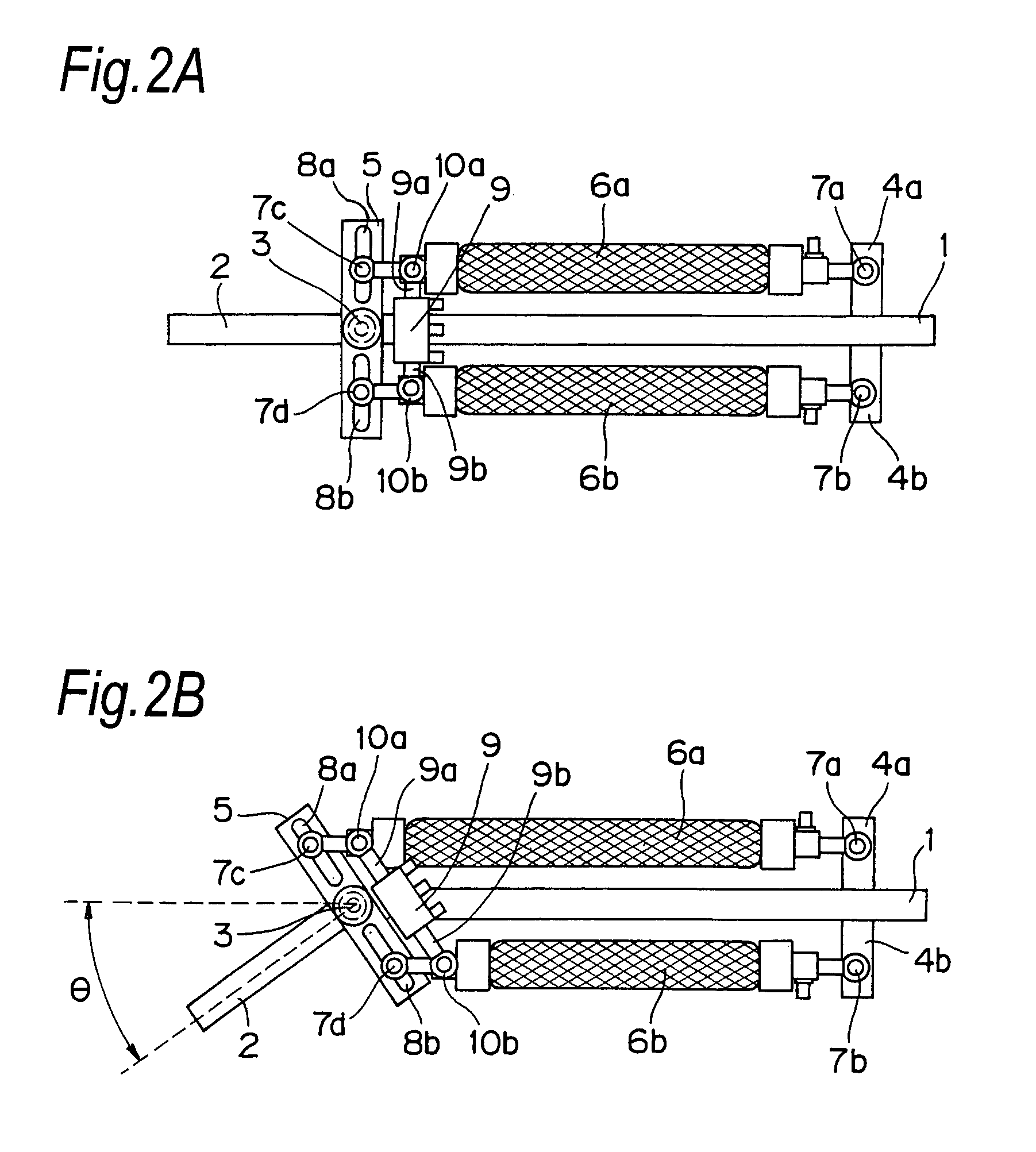
[0093]FIG. 1 is an overall view illustrating the configuration of a joint driving device according to a first embodiment of the present invention. In FIG. 1, numeral 1 denotes a rod-shaped first configuration member and numeral 2 denotes a rod-shaped second configuration member. The first configuration member 1 and the second configuration member 2 are coupled to each other at their one ends through a rotational joint 3 so that the first configuration member 1 and the second configuration member 2 are rotatable relative to each other. A pair of plate-shaped actuator supporting members 4a and 4b are placed on the other end of the first configuration member 1, such that the plate-shaped actuator supporting members 4a and 4b are located along the direction orthogonal to the axial direction of the first configuration member 1 and opposite to each other. Near one end of the second configuration member 2, there is placed a single plate-shaped actuator driving-force transfer member 5, alon...

second embodiment

[0129]FIGS. 9A and 9B are views illustrating the configuration of a joint driving device according to a second embodiment of the present invention. The joint driving device of FIGS. 9A and 9B is different from the first embodiment in components which will be described later, while the other portions are the same as those of the first embodiment. These common components will be designated by the same reference characters as those of the first embodiment and detailed description thereof will be omitted.

[0130]In FIGS. 9A, 9B, and 10, a numeral 45 is an elliptical-plate shaped cam which is placed such that the center shaft thereof is coincident with the rotation shaft of a rotational joint 3 and the cam is not relatively rotatable with respect to a first configuration member 1. A numeral 46 is a spring which is coupled to the end portions of the elastic body actuators 6a and 6b near the rotational joint 3 through rotation joints 47a and 47b. Further, the end portions of the elastic body...

third embodiment

[0137]FIG. 11 is a perspective view illustrating the configuration of a joint driving device according to a third embodiment of the present invention. In FIG. 11, a numeral 50 is a cam driving actuator which is operated under the control of the control computer 24 and is constituted by, for example, a rotational motor such as a DC servo motor, or a rotation type pneumatic actuator. The cam driving actuator 50 is secured to the actuator driving-force transfer member 5, and a cam 45 is secured to the output rotation shaft of the cam driving actuator 50. The rotational angle of the cam 45 relative to the actuator driving-force transfer member 5 can be controlled under the control of the control computer 24, through the cam driving actuator 50. The other configurations are similar to those of the aforementioned second embodiment and, therefore, the common components will be designated by the same reference characters and description thereof will be omitted.

[0138]In the joint driving dev...


PUM


Abstract

A first elastic body actuator and a second elastic body actuator are used for driving a first configuration member and a second configuration member to swing them with respect to each other. One end portion of the first elastic body actuator is secured to the first configuration member and the other end portion of the first elastic body actuator is secured to the second configuration member, and one end portion of the second elastic body actuator is secured to the first configuration member and the other end portion of the second elastic body actuator is secured to the second configuration member, such that the position at which the other end portion of the second elastic body actuator is secured to the second configuration member and the position at which the one end portion of the first elastic body actuator is secured to the second configuration member are substantially symmetric about a rotational joint. The interval between the portion of the first elastic body actuator, which is secured to the second configuration member, and the portion of the second elastic body actuator, which is secured to the second configuration member, is moved by a securing-position variable mechanism.

Description

[0001]This is a continuation application of International Application No. PCT / JP2005 / 015902, filed Aug. 31, 2005.BACKGROUND OF THE INVENTION[0002]The present invention relates to a joint driving device applicable to a joint mechanism for a mechanical apparatus such as a robot arm, and also relates to a robot arm including the joint driving device.[0003]Elastic body actuators such as pneumatic artificial muscles can generate translation displacements, but can generate forces only in the direction of their contraction. Accordingly, when such an elastic body actuator is applied to a rotational joint mechanism for a movable mechanical apparatus such as a robot arm, an antagonistic driving mechanism as illustrated in FIGS. 14A and 14B is employed to realize rotational motions.[0004]In FIGS. 14A and 14B, a numeral 57 denotes a first configuration member and a numeral 58 denotes a second configuration member. The first configuration member 57 and the second configuration member 58 are coup...

Claims


Application Information

Patent Timeline
Patent Type & Authority Patents(United States)
IPC IPC(8): B25J17/00
CPCB25J9/1075B25J9/142F15B15/103Y10T74/2036Y10T74/20329
Inventor OKAZAKI, YASUNAO
Owner PANASONIC CORP
Why Eureka
Try Eureka