Fixing device comprising a rotary drive for a gripper tool

a technology of fixing device and gripper tool, which is applied in the direction of mechanical machines/dredgers, load-engaging elements, soil shifting machines/dredgers, etc., can solve the problem that the impact cannot be passed on to the shaft of the hydromotor

Inactive Publication Date: 2006-10-12
VOULGARIS CHRISTOS
View PDF2 Cites 12 Cited by
  • Summary
  • Abstract
  • Description
  • Claims
  • Application Information

AI Technical Summary

Benefits of technology

[0004] The object of the invention is to embody the device of the type cited in the foregoing such that a long service life is assured for the hydromotor during rough continuous operation with impact-like stresses to the adapter plate in changing directions.
[0006] Thus from a static point of view the inventive solution is a complete departure from the known design. That is, the adapter plate is borne on the housing of the device and thus is fixed and supported radially. The purpose of the driven flange now is more for causing the adapter plate to move rotationally. Impacts that act on the adapter plate in the oblique direction are conducted from outside into the stable housing and are safely absorbed there. But the impacts cannot be passed on to the shaft of the hydromotor because the driven flange and the adapter plate are no longer flush against one another but rather are situated at an axial distance from one another. In contrast to the known design, therefore, the hydromotor can be of lighter construction. Yet a substantially increased service life is attained for the hydromotor.
[0009] This bearing is advantageously performed in accordance with another embodiment in that a deep-groove ball bearing is provided between the exterior circumference of the housing and the interior circumference of the annular flange. Given the relatively large diameter of the housing and the annular flange that encircle the hydromotor, the deep-groove ball bearing can be very heavily stressed, even if the balls in the bearing are not very large.
[0010] Statically, it is particularly advantageous when the annular flange and the adapter plate are embodied as a single piece. However, cost-effective production is possible when the annular flange and the adapter plate are separate plates and are bolted together.
[0011] The axial extension of the entire device can be reduced when in accordance with another advantageous embodiment the driven flange is received in a depression on the inside of the adapter plate.

Problems solved by technology

But the impacts cannot be passed on to the shaft of the hydromotor because the driven flange and the adapter plate are no longer flush against one another but rather are situated at an axial distance from one another.

Method used


Image

  • Fixing device comprising a rotary drive for a gripper tool
  • Fixing device comprising a rotary drive for a gripper tool
  • Fixing device comprising a rotary drive for a gripper tool

Examples


Embodiment Construction

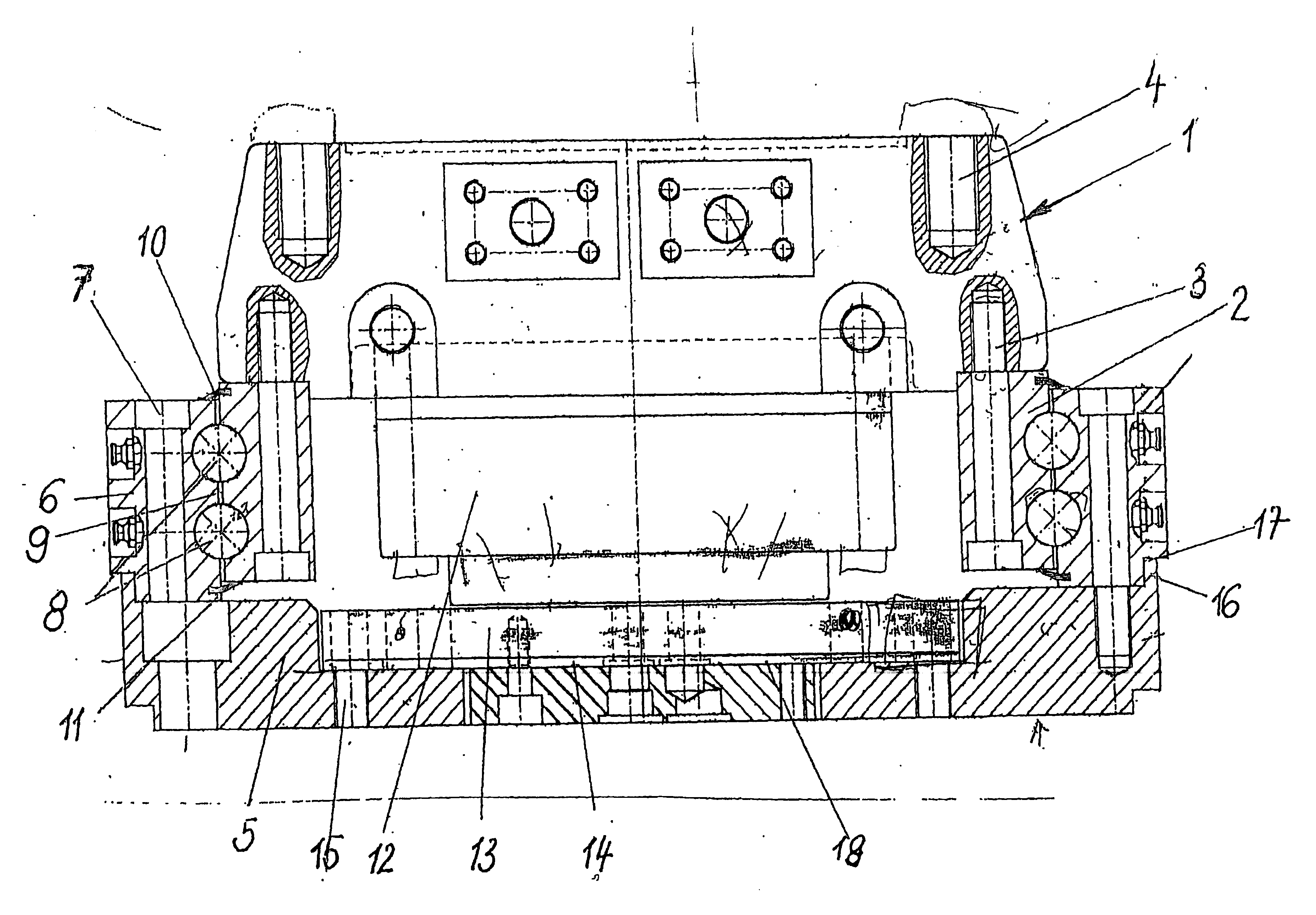
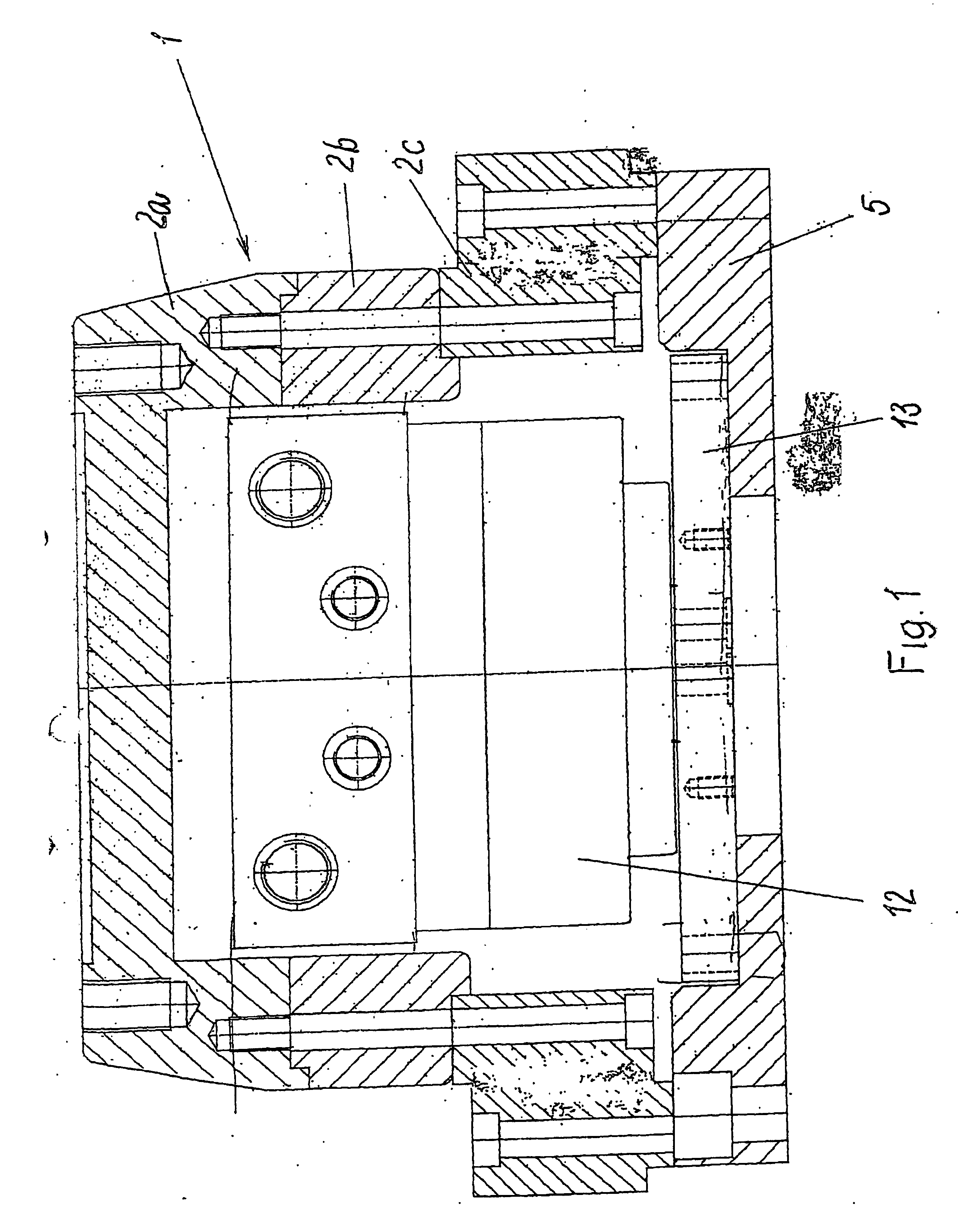
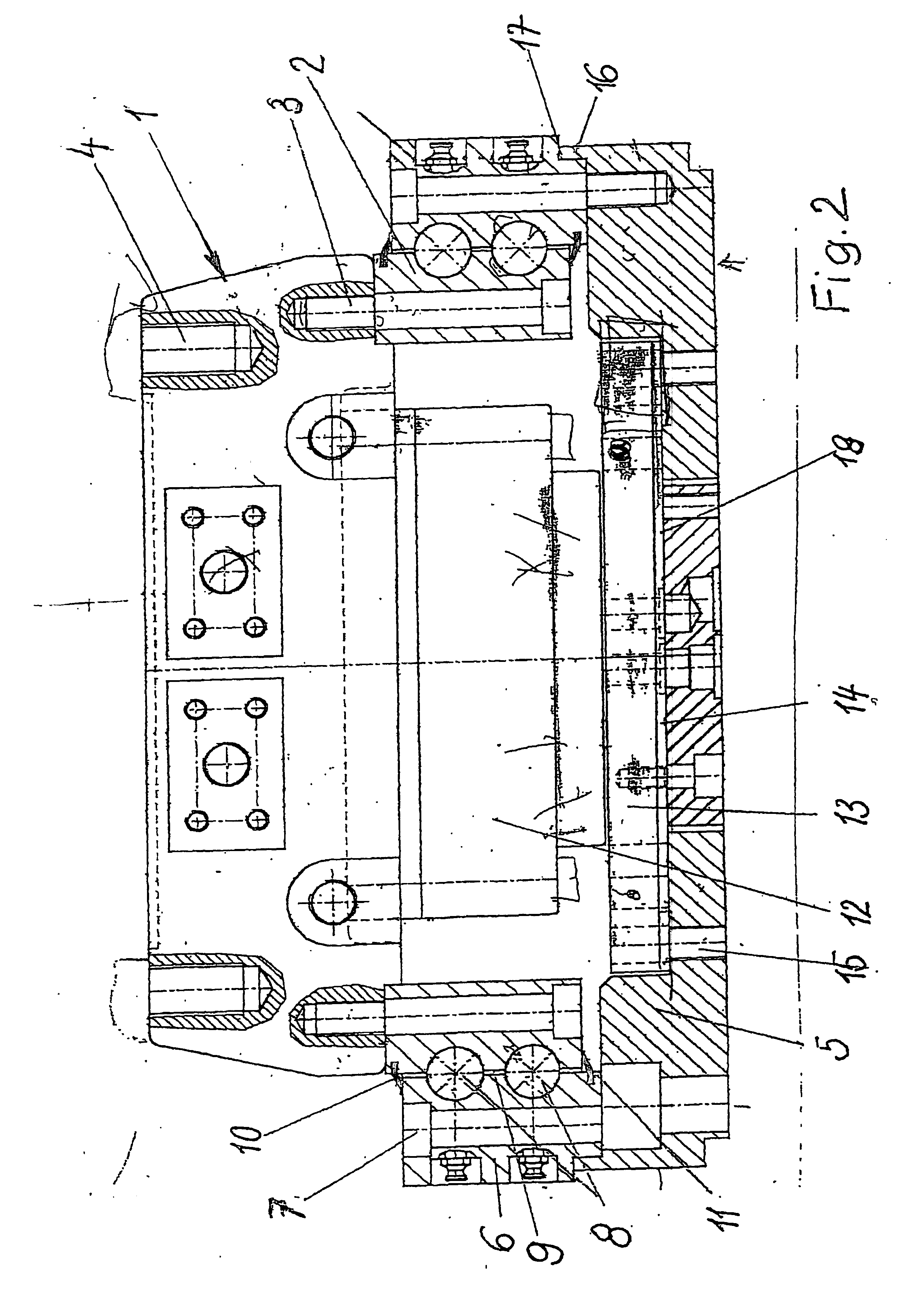
[0017] As has already been stated in the foregoing, a device for attaching and for rotary drive of a gripping tool or the like has a housing 1 that is constructed from the annular housing parts 2a, 2b, and 2c. These housing parts are securely bolted to one another. A hydromotor 12 is inserted rotation-fast in the housing and attached using means that are not shown. The hydromotor drives a driven flange 13 that itself is bolted to an adapter plate 5. In this device known from the prior art the driven flange 13 and the adapter plate 5 are flush against one another. However, depending on installation tolerances, the adapter plate 5 can also be in contact with the end face of the housing part 2.

[0018] This device is attached by means of the housing part 2a to the boom of a crane, excavator, or similar conveying and lifting machine. Thus, the adapter plate 5 carries the gripping tool and causes it to move rotationally for working as soon as the hydromotor 12 is actuated.

[0019] The know...


PUM


Abstract

A device for fixing and rotationally driving a gripper tool or the like on the arm of a crane, an excavator or a similar transporting and lifting machine is disclosed. The device includes a housing. An adapter plate including an annular flange is arranged on the housing, the flange being rotatable about the housing by a grooved ball bearing. The housing includes a hydromotor which transmits the rotational movement thereof to the adapter plate by an output flange. The output flange and the adapter plate are axially distanced from each other. Screw bolts transfer the rotary driving force between the output flange and the adapter plate.

Description

BACKGROUND OF THE INVENTION [0001] The invention relates to a device for attaching and for rotary drive of a gripping tool or the like on the boom of a crane, excavator, or a similar conveying and lifting machine, with a housing attached to the boom, the housing receives in its interior a hydromotor with a driven flange and on the side of the gripping tool has an adapter plate that is for attaching the gripping tool and is driven to rotate by the driven flange. [0002] Such a device is known from the operational practice of Applicant. It is schematically illustrated in the exemplary embodiment in FIG. 1. In accordance with it, the device has a housing 1 that is made of the parts 2a, 2b, and 2c bolted together. A hydromotor 12 is inserted rotation-fast in this housing. The hydromotor is driven by a hydraulic fluid that is conducted into and out of the interior of the hydromotor via lines (not shown). The shaft of the hydromotor generally performs only short rotating movements that rot...

Claims


Application Information

Patent Timeline
Patent Type & Authority Applications(United States)
IPC IPC(8): E02F3/96B66C3/00E02F3/36
CPCE02F3/3677B66C3/005
Inventor VOULGARIS, CHRISTOS
Owner VOULGARIS CHRISTOS
Why Eureka
Try Eureka