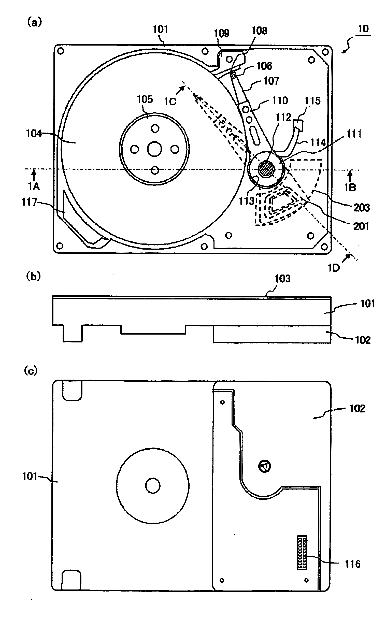
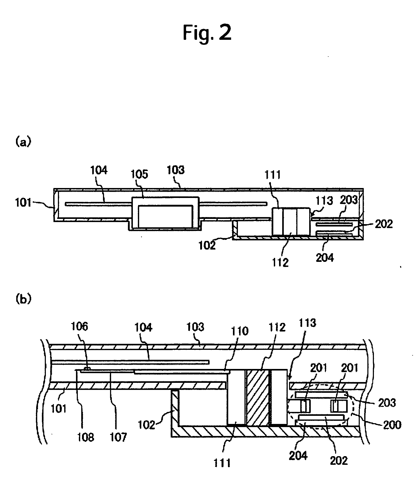
[0031] A first embodiment of the present invention is an LUL type of magnetic disk drive to which the invention is applied. A general view of magnetic disk drive 10 according to the present embodiment is shown in FIG. 1. FIG. 1(a) is a front view of the magnetic disk drive 10 with a top cover 103 removed, FIG. 1(b) a side view of the magnetic disk drive 10, and FIG. 1(c) a bottom view thereof.
[0032] As shown in FIG. 1(b), the magnetic disk drive 10 is constructed so that a disk compartment enclosure 101 and a VCM compartment enclosure 102 are separated from each other and so that the VCM compartment enclosure 102 is secured to the bottom of the disk compartment enclosure 101. In this figure, a magnetic disk 104, a spindle motor (SPM) 105, a slider 106, a suspension 107, a head arm 110, and other elements are stored within the disk compartment enclosure 101. Also, components of a VCM 200, such as VCM coils 201 and a top yoke 203, are stored within the VCM compartment enclosure 102. That is to say, the bottom of the disk compartment enclosure 101 plays a role of an isolation wall which separates the magnetic disk 104 and the VCM components such as the VCM coils 201. As can be seen from this, the magnetic disk drive 10 is characterized in that the magnetic disk 104 and the VCM are isolated from each other by an isolation wall approximately parallel to a recording surface of the magnetic disk 4.
[0033] The components accommodated in the disk compartment enclosure 101 are described below referring to FIG. 1(a). The magnetic disk 104 is secured to a hub of the SPM 105. The SPM 105 rotates the magnetic disk 104 at a required speed. The SPM 105 is driven by a motor drive unit (MDU) provided outside the disk compartment enclosure 101. The MDU, together with other ICs such as a hard-disk controller (HDC), an MPU, and a read/write (R/W) channel, is mounted on a circuit board (not shown). The circuit board is provided in such a way as to form the bottoms of the disk compartment enclosure 101 and the VCM compartment enclosure 102.
[0034] A head (not shown) that writes data onto and reads it out from the magnetic disk 104 is provided at a front end of the slider 106. The slider 106 is fixed to the suspension 107, which is further fixed to the head arm 110. At a front end of the suspension 107 is provided a tab 108, which, by getting on a ramp 109, moves the slider 106 away from the magnetic disk 104.
[0035] The head arm 110 has a bearing 111 installed in the state where it can pivot about a pivot shaft 112. The bearing 111 of the head arm 110 and the pivot shaft 112 are arranged in a penetrating form in a circular opening 113 provided at the bottom of the disk compartment enclosure 101, and the head arm 110 is integrated with the VCM coils 201 accommodated in the VCM compartment enclosure 102. The pivot shaft 112 is fixed to the VCM compartment enclosure 103. In order to keep dust from flowing from the VCM compartment via the opening 113 into the disk compartment, a labyrinth seal that generates flow path resistance and suppresses the inflow of dust may be provided between the bearing 111 and the opening 113.
[0036] A cable, that connects the head located at the front end of the slider 106 and a head amplifier (not shown) that is provided in the VCM compartment enclosure 102, is provided as a flexible printed cable (FPC) 114. The FPC 114 has one end passed through an opening 115 within a lower face of the disk compartment enclosure 101 and connected to a connector inside the enclosure 101. The connector establishes connection to the circuit board on which are mounted the HDC, the R/W channel, the MDU, and other components. The head amplifier may be provided near the head arm, on the FPC 114. In this case, the FPC 114 will be a cable connecting the head amplifier and the R/W channel. The opening 115 is sealed to prevent dust from flowing in from the VCM compartment enclosure 102.
[0037] Finally, air filter 117 removes internal dust from the disk compartment enclosure 102 by utilizing the air stream generated by the rotation of the magnetic disk 104.
[0038] Next, the relationship in position between the magnetic disk 104 and VCM 200 that the magnetic disk drive 10 has will be described below using FIG. 2. FIG. 2(a) is a sectional view of the magnetic disk drive 10, taken along straight line 1A-1B in FIG. 1(a). FIG. 2(b) is a sectional view of the magnetic disk drive 10 existing when the slider 106 is positioned under the magnetic disk 104 by pivoting the head arm 110. The section taken along straight line 1C-1D in FIG. 1(a) is shown in this sectional view.
[0039] The VCM 200 is constituted by the VCM coils 201 fixed to the bearing 111 of the head arm 110, a magnet 202, a top yoke 203, and a bottom yoke 204. Supplying an electric current to the VCM coil 201 exerts a magnetic field of the magnet 202 upon the VCM coil 201, pivots the head arm 110 about the pivot shaft 112, and causes the head fixed to the slider 106 to be loaded for positioning above the surface of the magnetic disk 104.
[0040] As shown, the VCM 200 and the magnetic disk 104 are isolated from each other by the bottom of the disk compartment enclosure 101. The bearing 111 of the head arm 110 is disposed in a penetrating form in the opening 113 provided at the bottom of the disk compartment enclosure 101. The VCM coil 201 is installed on the VCM compartment side, which is an underside of the bearing 111, and the suspension 107 is fixed to the disk compartment side, which is an upper side of the bearing 111.
[0041] Such a construction makes it possible to transmit driving force of the VCM 200 to the head arm 110 in spite of the magnetic disk 104 and the VCM 200 being isolated from each other by the isolation wall parallel to the recording surface of the magnetic disk 104.
[0042]FIG. 3 is a view in which the components shown in the plan view of FIG. 1(a), such as the magnetic disk 104 and the head arm 104, are omitted to show the openings 113 and 115 provided at the bottom of the disk compartment enclosure 101. FIG. 3 is therefore a view equivalent to a plan view of the disk compartment enclosure 101 existing before it is assembled. As shown in FIG. 3(a), the opening 113 has a circular shape so that the head arm 110 can pivot about the pivot shaft 112. There are no limitations on a shape of the opening 115.
[0043]FIG. 3(b) shows the opening 113 whose shape is changed for easier assembly of the magnetic disk drive 10. Providing an opening of this shape allows the magnetic disk drive 10 to be easily assembled after a rear end of the head arm 110 integrated with the VCM coils 201 has been installed on the pivot shaft 112 fixed to the VCM compartment enclosure 103. The section of the opening 113 that is expanded to allow the suspension 107, the head arm 110, and other components to be passed through, can be sealed with a sealing material.
[0044] As described above, the magnetic disk 104 and the VCM 200 are isolated from each other by an isolation wall approximately parallel to the recording surface of the magnetic disk 104, and the head arm 110 is actuated about the pivot shaft 112 that penetrates the circular opening 113 provided in the isolation wall. This construction allows the adoption of the LUL scheme that has traditionally not been adoptable in the construction having an isolation wall(s) vertical to the recording surface of the magnetic disk 104, as in the conventional magnetic disk drive 50. As will be detailed in the later-described second embodiment of the present invention, it is also possible to adopt a construction having the VCM 200 positioned internally to the outer circumference of the magnetic disk 104.
[0045] The conventional magnetic disk drive 50 is of the construction in which the VCM 504 and the magnetic disk 505 are isolated by the upstream isolation wall 507 and downstream isolation wall 508 provided vertically to the recording surface of the magnetic disk 505, and by the arm pivot shaft 503. In this construction, therefore, the air stream parallel to the magnetic disk recording surface, generated by the rotation of the magnetic disk 505, has easily flown into the clearances between the upstream isolation wall 507 and the arm pivot shaft 503 and between the downstream isolation wall 508 and the arm pivot shaft 503.
[0046] In contrast to the above, the magnetic disk drive 10 is constructed so that it has the opening 113 in an isolation wall approximately parallel to the recording surface of the magnetic disk 104. Therefore, a direction of flow of the air stream generated by the rotation of the magnetic disk 104 and the isolation wall are maintained in a parallel relationship, which prevents the air stream from easily flowing into the opening 113. For this reason, the magnetic disk drive 10, compared with the conventional magnetic disk drive 50, can enhance the magnetic disk compartment and the disk compartment in separability, thus further reducing the flow of dust from the VCM compartment into the magnetic disk compartment.
[0047] While, as shown in FIG. 2(b), the magnetic disk drive 10 of the present embodiment is adapted to use a lower face of the magnetic disk 104 as the recording surface, the disk drive 10 can also be constructed so that the head is loaded for positioning at an upper face of the magnetic disk 104. In addition, as is traditionally conducted, both the upper and lower faces of the magnetic disk 104 can be used as recording surfaces by taking a stacked arrangement of head arms 110. It goes without saying that the present invention can be applied even in a construction having a stacked arrangement of even more head arms 110 and a plurality of magnetic disks 104.