
Simultaneous optical flow estimation and image segmentation

a flow estimation and image technology, applied in the field of simultaneous optical flow estimation and image segmentation, can solve the problems of inability to recover from segmentation process errors, inability to use flow-based segmentation to achieve the effect of avoiding the inability to accurately predict the effect of motion estimation, and inherently ill-posed motion estimation

Inactive Publication Date: 2006-10-12
MICROSOFT TECH LICENSING LLC
View PDF17 Cites 15 Cited by
  • Summary
  • Abstract
  • Description
  • Claims
  • Application Information

AI Technical Summary

Benefits of technology

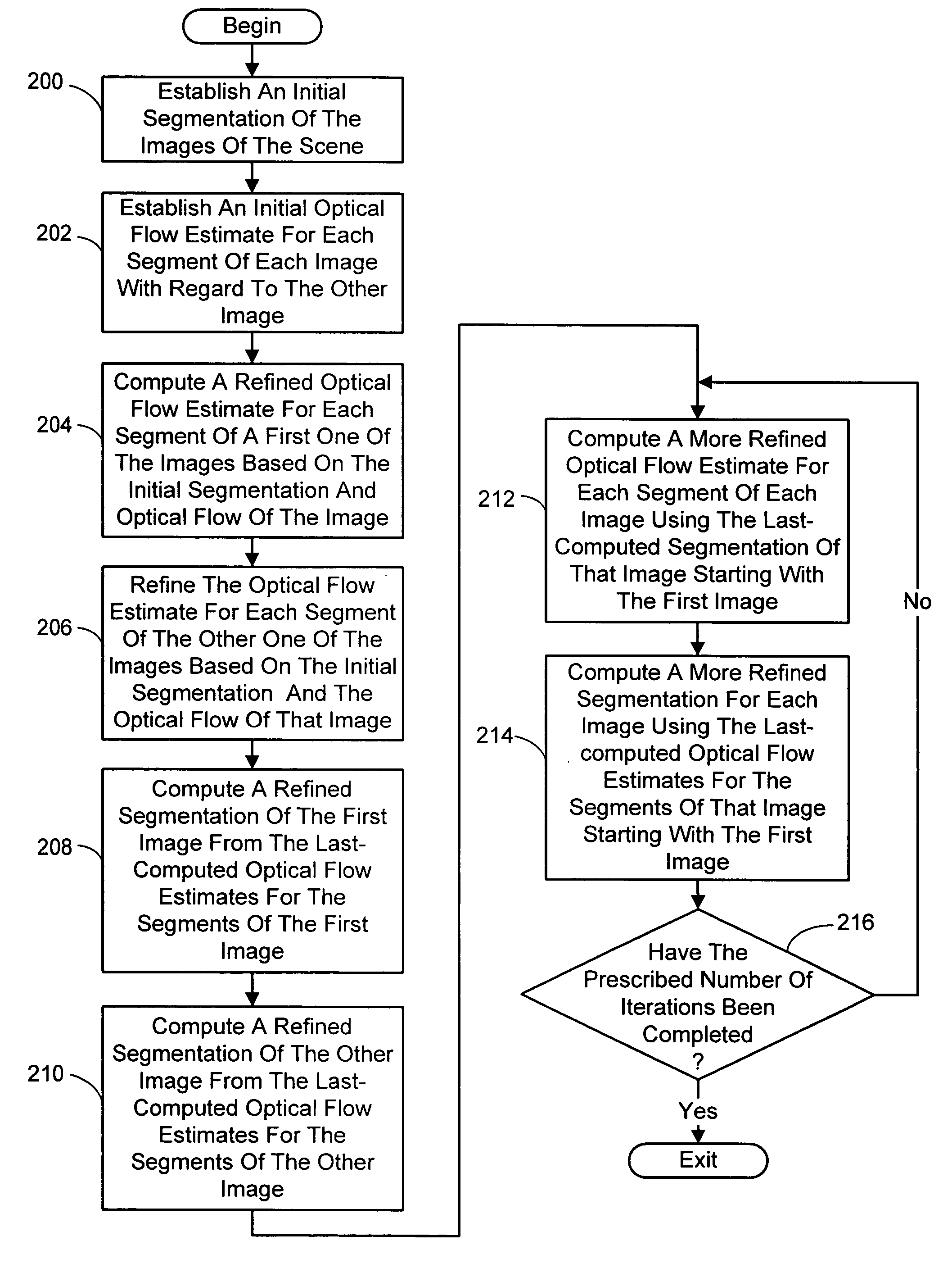
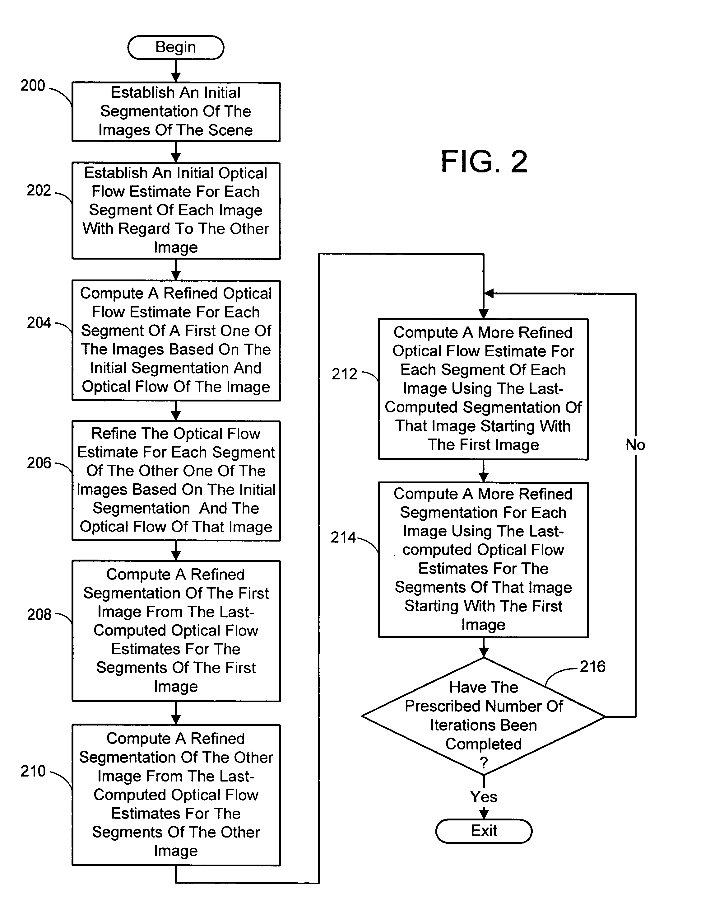
[0006] The present invention is directed toward an improved technique for estimating the optical flow between images of a scene and a segmentation of the images. This involves first establishing an initial segmentation of the images of the scene and an initial optical flow estimate for each segment of the images. In one embodiment of the present technique, the image segmentation is initialized using the a quad-tree app

Problems solved by technology

Motion estimation is inherently ill-posed, and techniques ranging from regularization, use of global or parametric motion models, and segmentation have been used to reduce the problem.
However, these approaches use statically-determined segments for motion estimation.
The problem with using static color segments is the inability to recover from errors in the segmentation process.
Another challenge is the effect of discretization and area integration—pixels near texture or object boundaries are mixtures of foreground and background colors.
Unfortunately, results obtained using flow-based segmentation tend to be unpredictable at object boundaries due to the local aperture ambiguity.
One approach for joint segmentation and flow computation involved a patch-based technique, but this method is computationally expensive.

Method used


Image

  • Simultaneous optical flow estimation and image segmentation
  • Simultaneous optical flow estimation and image segmentation
  • Simultaneous optical flow estimation and image segmentation

Examples


Embodiment Construction

[0022] In the following description of the preferred embodiments of the present invention, reference is made to the accompanying drawings which form a part hereof, and in which is shown by way of illustration specific embodiments in which the invention may be practiced. It is understood that other embodiments may be utilized and structural changes may be made without departing from the scope of the present invention.

1.0 The Computing Environment

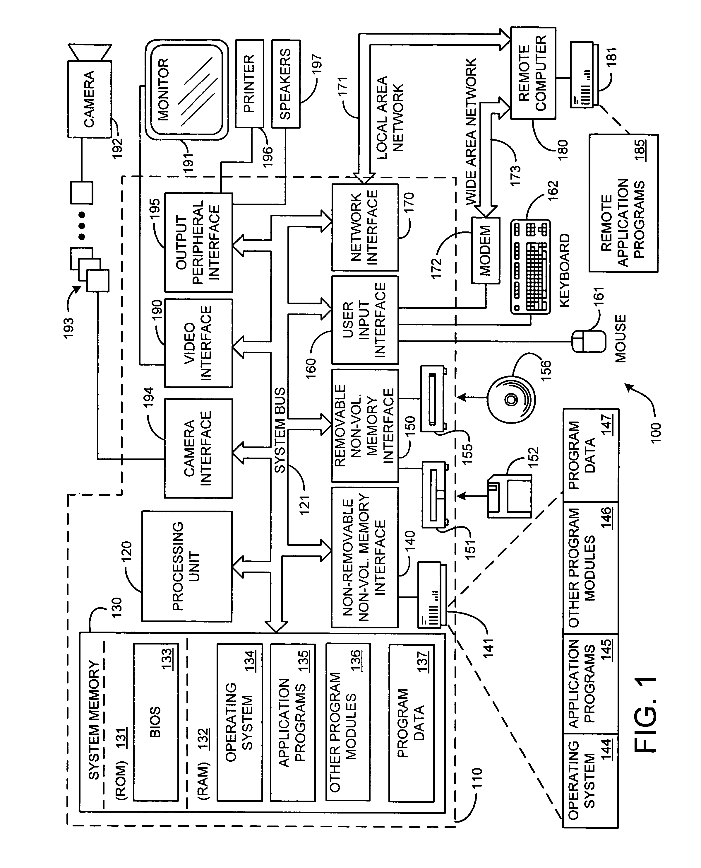
[0023] Before providing a description of the preferred embodiments of the present invention, a brief, general description of a suitable computing environment in which portions of the invention may be implemented will be described. FIG. 1 illustrates an example of a suitable computing system environment 100. The computing system environment 100 is only one example of a suitable computing environment and is not intended to suggest any limitation as to the scope of use or functionality of the invention. Neither should the computing environmen...


PUM


Abstract

A technique for estimating the optical flow between images of a scene and a segmentation of the images is presented. This involves first establishing an initial segmentation of the images and an initial optical flow estimate for each segment of each images and its neighboring image or images. A refined optical flow estimate is computed for each segment of each image from the initial segmentation of that image and the initial optical flow of the segments of that image. Next, the segmentation of each image is refined from the last-computed optical flow estimates for each segment of the image. This process can continue in an iterative manner by further refining the optical flow estimates for the images using their respective last-computed segmentation, followed by further refining the segmentation of each image using their respective last-computed optical flow estimates, until a prescribed number of iterations have been completed.

Description

CROSS-REFERENCE TO RELATED APPLICATIONS [0001] This application claims the benefit of a previously-filed provisional patent application Ser. No. 60 / 669,675 on Apr. 8, 2005.BACKGROUND Background Art [0002] Motion estimation is inherently ill-posed, and techniques ranging from regularization, use of global or parametric motion models, and segmentation have been used to reduce the problem. The approach of pre-segmenting images based on color similarity and estimating the motion of segments has been shown to be effective. Such approaches depend on the reasonable assumption that similarly colored neighboring pixels have similar motions (or depths). However, these approaches use statically-determined segments for motion estimation. [0003] The problem with using static color segments is the inability to recover from errors in the segmentation process. Ideally, the shape of segments should evolve based on spatial-temporal evidence. Another challenge is the effect of discretization and area ...

Claims


Application Information

Patent Timeline
IPC IPC(8): G06K9/00G06V10/26G06V10/28G06V10/56
CPCG06K9/34G06K9/6219G06K9/4652G06K9/38G06V10/26G06V10/28G06V10/56G06V10/7625G06F18/231
Inventor ZITNICK, CHARLES IIIKANG, SING BINGJOJIC, NEBOJSA
Owner MICROSOFT TECH LICENSING LLC
Learn More