
Plastic optical fibers and processes for producing them

Inactive Publication Date: 2006-10-12
FUJIFILM HLDG CORP +1
View PDF2 Cites 3 Cited by
  • Summary
  • Abstract
  • Description
  • Claims
  • Application Information

AI Technical Summary

Benefits of technology

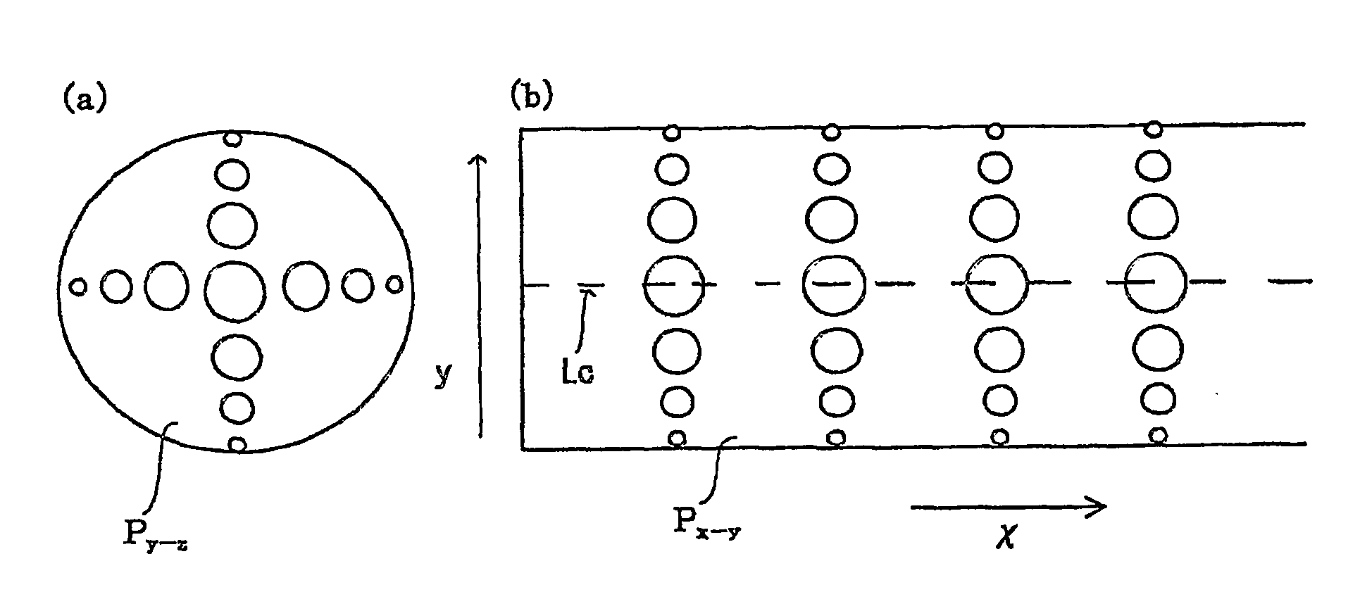
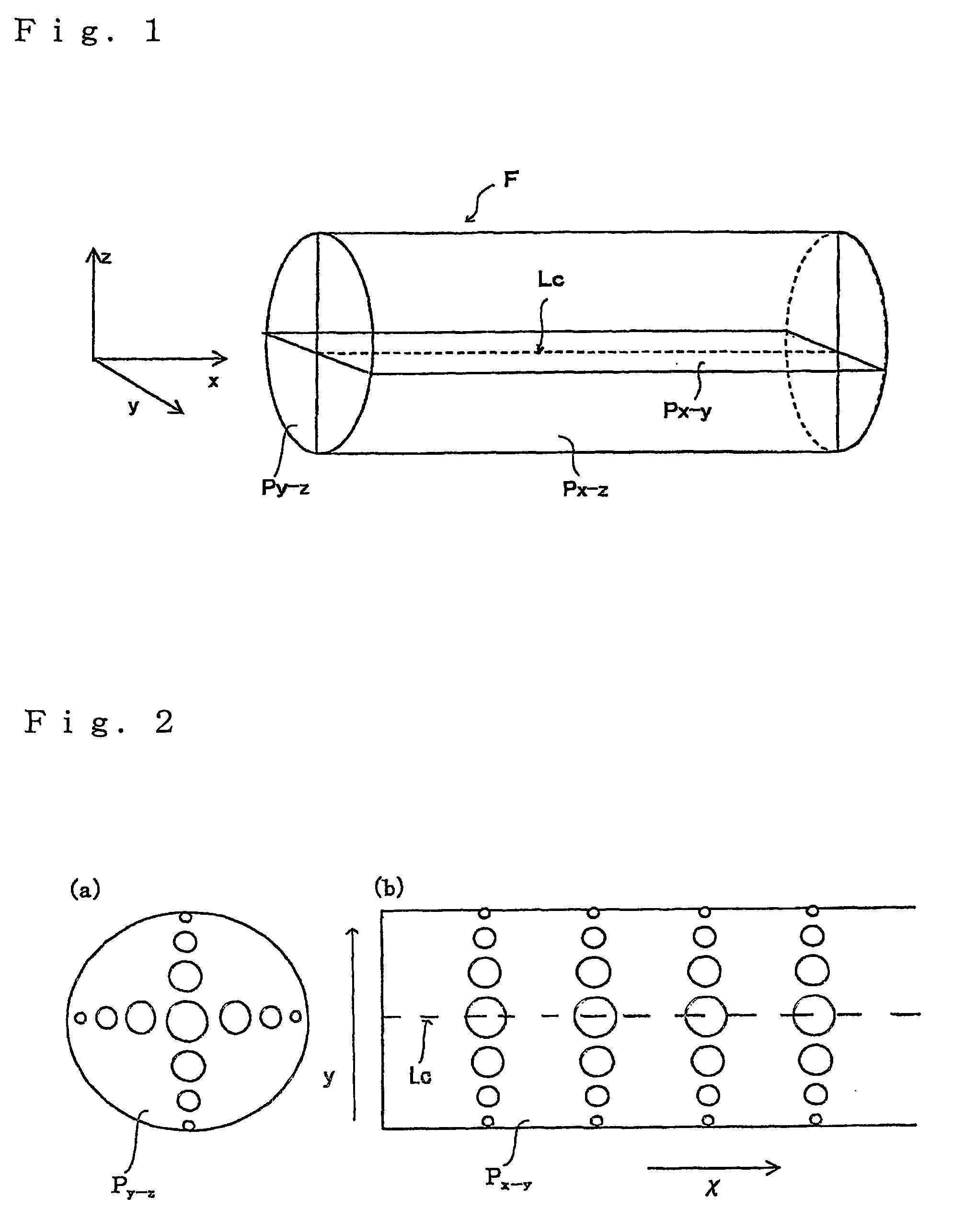
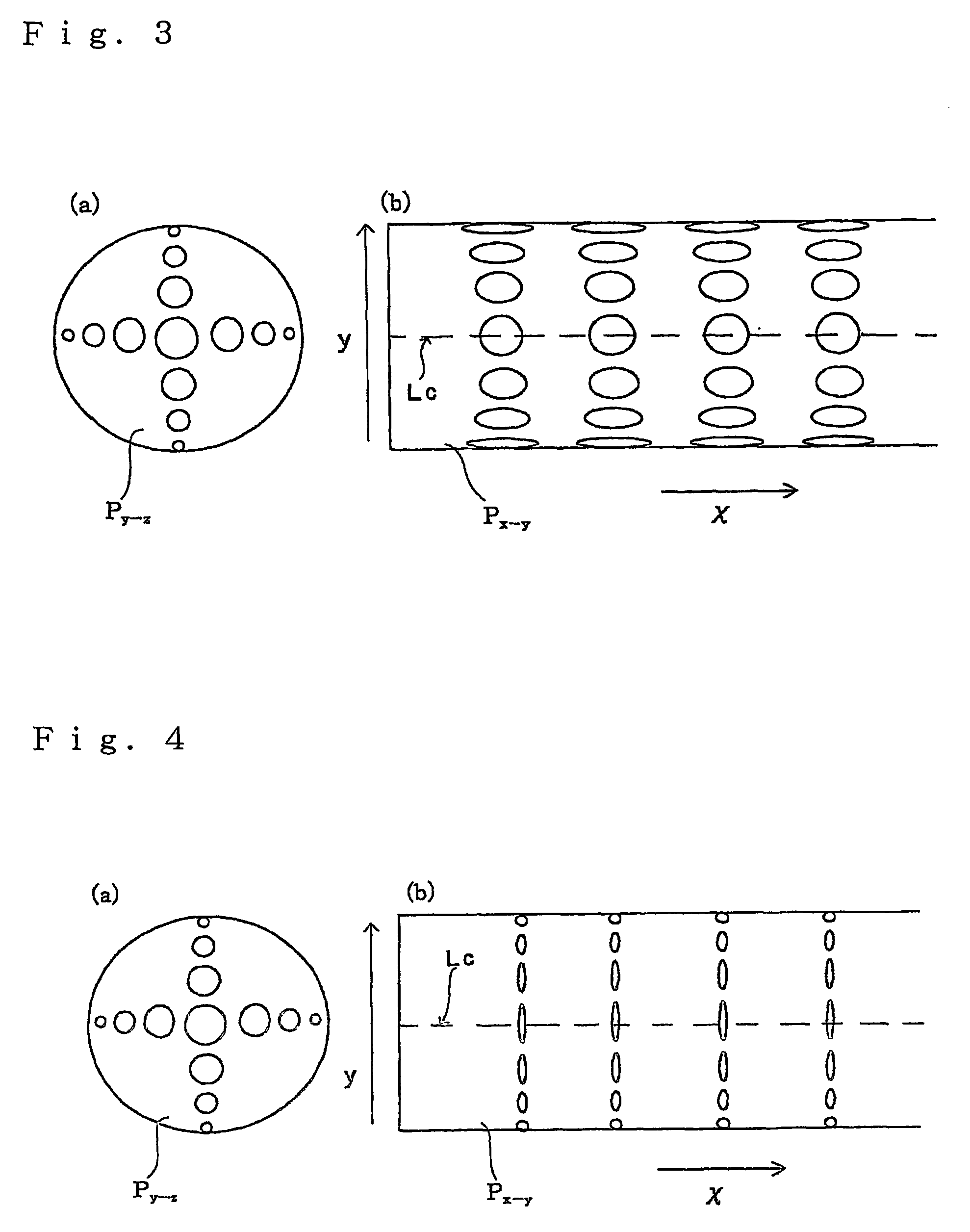
[0013] The multimode optical fiber of the present invention can be produced by creating a retardation distribution in any plane parallel to the light-propagating direction and containing the center line along the longitudinal axis of the fiber, thereby causing a refractive index distribution, which is required for improvement in optical fiber bandwidth, in any plane perpendicular to the light-propagating direction. According to the present invention, multimode optical fibers can be produced by using a uniform composition, and the refractive index profile may be hardly disordered due to temperature and humidity variations compared with the conventional refractive index prof

Problems solved by technology

However, according to the above mentioned process for producing GI type optical plastic fibers, an accurate reaction control is required for producing a preform, and it is difficult to control reaction conditions during producing.
Especially, according to the process disclosed in JPA No 1986-130904, using interfacial-gel polymerization, it takes a long time to develop a preform gradually radially, and size such as length or diameter of the obtained preform may be limited.
It is thus difficult to reduce the production cost for a step of producing a preform or a step of drawing the preform.
However, the present inventors conducted various studi

Method used


Image

  • Plastic optical fibers and processes for producing them
  • Plastic optical fibers and processes for producing them
  • Plastic optical fibers and processes for producing them

Examples


Example

[0107] A preform was produced in the same manner as Example 1.

(Drawing)

[0108] The obtained preform was drawn by a drawing machine comprising a ring-shaped electric furnace, having a same construction as shown in FIG. 9. The temperatures of the first and second compartments were set to 140 and 180° C. respectively, the temperature of the third compartment was set to 240° C. and the temperatures of the fourth and fifth compartments were set to 170 and 140° C. respectively while the preform was drawn. A sample, or in other words a fiber having an outer diameter of 1 mm and a length of 50 m, of Comparative Example No. 1 was thus obtained.

[0109] Optical fiber bandwidth, birefringence index distribution and temperature and humidity stability of the obtained fiber were evaluated in the same manner as Example Nos. 1 to 9. The obtained results are shown in Table 1. It is to be noted that the sample of Comparative Example No. 1 had retardation however, and the amount of the retardation wa...

Example

Comparative Example No. 2

[0110] A GI-type plastic optical fiber was produced in the same manner as Example No. 4 described in Japanese Patent No. 3332922. In the process, which is known as a process for producing GI-type optical fibers, a dopant was used and the distribution in refractive index was created based on the distribution in concentration of the dopant. The properties of the obtained optical fiber were evaluated in the same manner as described above. TABLE 1Retardation (nm)Drawing-in centraltemperatureportion → inLight(thirdBandwidthperiphery portionlossSample No.compartment)(MHz)near to clad region(dB / km)Example 1205° C.380380→37015Example 2210° C.530380→36018Example 3215° C.890370→35016Example 4220° C.1150360→34019Example 5225° C.1540350→31014Example 6230° C.1240330→28017Example 7235° C.630280→25012Example 8240° C.340240→23017Example 9245° C.210150→14018Comparative240° C.105220→21016Example 1Comparative240° C.1430290→270260Example 2

INDUSTRIAL APPLICABILITY

[0111] Accor...


PUM


Abstract

A novel optical plastic fiber comprising a core region and having a center line along a longitudinal axis of the fiber is disclosed. The refractive index of the core region increases along a direction going from a periphery portion to the center line in any plane perpendicular to the center line, and the birefringence index of the core region varies along a direction going from the center line to a periphery portion perpendicular to the center line in any plane parallel to the center line and containing the center line.

Description

TECHNICAL FIELD [0001] The present invention relates to optical plastic fibers capable of propagating high-frequency signals having a bandwidth of higher than 10 GHz·m, and more specifically relates to graded-index (GI) type multimode plastic optical fibers improved in robustness and producing cost compared with the conventional GI type multimode plastic optical fibers. RELATED ARTS [0002] In the field of glass optical fibers, multimode is used as a mode of fibers capable connecting in the form of large diameter, and especially in the field of plastic optical fibers, multimode is used frequently as a basic mode. A plastic optical fiber, hereinafter occasionally referred as “POF” is slightly inferior to quartz-base fiber since the entire region of the element fiber thereof is made of plastic material and has, as a consequence, a little larger transmission loss, but superior to the quartz-base optical fiber in that having an excellent flexibility, lightweight property, workability, be...

Claims


Application Information

Patent Timeline
IPC IPC(8): G02B6/028G02B6/10
CPCB29D11/00663G02B6/105G02B6/02376G02B6/02038G02B6/00
Inventor KAMADA, KOU
Owner FUJIFILM HLDG CORP
Learn More