Pendulum-shaped microstrip antenna structure

Inactive Publication Date: 2008-07-31
ALPHA NETWORKS INC
View PDF7 Cites 5 Cited by
  • Summary
  • Abstract
  • Description
  • Claims
  • Application Information

AI Technical Summary

Benefits of technology

[0007]Therefore, it is a primary objective of the present invention to provide a pendulum-shaped microstrip antenna structure, and the pendulum-shaped antenna is manufactured in form of a metal microstrip on a side of the printed circuit board and installed at a distal end of the printed circuit board, when the pendulum-shaped antenna is installed onto a printed circuit board of a wireless electronic product. The pendulum-shaped microstrip antenna structure comprises a signal feeding portion and an antenna portion sequentially installed in the direction from the printed circuit board to its distal end, and the pendulum-shaped antenna is extended outward, so that the current transmitted from the pendulum-shaped antenna can be distributed uniformly onto the signal feeding portion and the antenna portion to achieve the effects of improving the bandwidth of the pendulum-shaped antenna, reducing the feeding inductance, and providing sufficient bandwidth.

Problems solved by technology

As present wireless electronic products having a USB interface tend to be developed with a thin, light, short and compact design, the space reserved for an antenna unit in the wireless electronic product becomes increasingly smaller, and thus the position of the antenna unit in the wireless electronic product is very limited.
However, the chip antenna cannot be installed onto a circuit board according to the best condition of the practical application, because the chip antenna has to cope with different external mechanisms of the wireless electronic product and coefficients of the circuit board, so that the chip antenna has to employ extra capacitors and inductors.
Furthermore, the dielectric coefficient of the chip antenna is too large due to the material of the chip antenna, and thus the problem of having insufficient bandwidth for the application of the chip antenna may arise, and the performance of the chip antenna may be lowered.
Chip antennas of this sort require additional costs, and incur a higher overall cost of the wireless electronic product.
However, the wireless electronic product may have a dead corner in its use; and as a result, the wireless signal cannot be received effectively.
The limitations include the feasibility of mass production and after-sale maintenance as well as the level of difficulty for adjusting the bandwidth of an antenna unit, and only the horn-shaped antenna unit 71 can accommodate these limitations and fit the application better.
If it is necessary to improve the bandwidth performance of the horn-shaped antenna unit 71, the area of the antenna unit 71 on the circuit board 70 and the cost of the antenna unit 71 must be increased, and thus making it very difficult for manufacturers to control the cost.
However, the design of a multi-channel feed line 82 is relatively difficult, and requires accurate estimations on the interactive coupling effect of the microstrip line and any change brought by the impedance of the microstrip line.
Therefore, it is an important issue for antenna designers and manufacturers to develop a microstrip antenna structure to overcome the aforementioned shortcomings.

Method used


Image

  • Pendulum-shaped microstrip antenna structure
  • Pendulum-shaped microstrip antenna structure
  • Pendulum-shaped microstrip antenna structure

Examples


Embodiment Construction

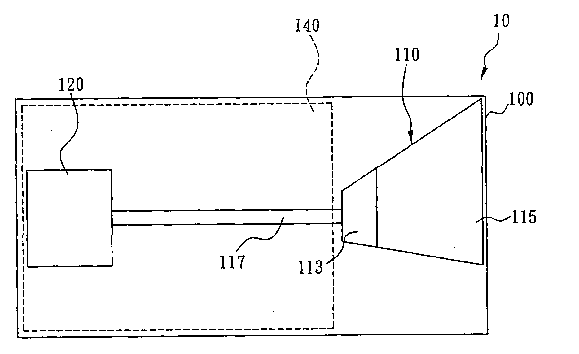
[0018]Referring to FIGS. 6 and 7 for a pendulum-shaped microstrip antenna structure of the present invention, the pendulum-shaped antenna 110 in the form of a metal microstrip is installed onto a printed circuit board 100 of a wireless electronic product by a printed circuit manufacturing technology, so that the pendulum-shaped antenna 110a is manufactured at an appropriate position on a surface of the printed circuit board 100, and the printed circuit board 100 further installs a control circuit and required components of a wireless electronic product, and the pendulum-shaped antenna 110 includes a signal feeding portion 113 and an antenna portion 115, and both signal feeding portion 113 and antenna portion 115 are in a trapezium shape, but the area of the antenna portion 115 is larger than the area of the signal feeding portion 113, such that a shorter side of the antenna portion 115 is connected to a longer side of the signal feeding portion 113 to form the pendulum-shaped antenn...


PUM


Abstract

The present invention discloses a pendulum-shaped microstrip antenna structure which is manufactured in form of a metal microstrip on a side of the printed circuit board and installed at a distal end of the printed circuit board, when the pendulum-shaped antenna is installed onto a printed circuit board of a wireless electronic product. The pendulum-shaped microstrip antenna structure includes a signal feeding portion and an antenna portion sequentially installed in the direction from the printed circuit board to its distal end, and the pendulum-shaped antenna is extended outward, so that a current transmitted from the pendulum-shaped antenna can be distributed uniformly onto the signal feeding portion and the antenna portion to achieve the effects of improving the bandwidth of the pendulum-shaped antenna, reducing the feeding inductance, and providing sufficient bandwidth for the antenna.

Description

FIELD OF THE INVENTION[0001]The present invention relates to a microstrip antenna structure, and more particularly to a pendulum-shaped microstrip antenna structure for improving the bandwidth of the antenna, reducing the feeding inductance, and providing sufficient bandwidth.BACKGROUND OF THE INVENTION[0002]As present wireless electronic products having a USB interface tend to be developed with a thin, light, short and compact design, the space reserved for an antenna unit in the wireless electronic product becomes increasingly smaller, and thus the position of the antenna unit in the wireless electronic product is very limited. In general, the antenna unit for the wireless electronic product is a chip antenna produced by a low temperature cofired ceramic technology, and the chip antenna has the features of small size and flexibility for its installation in the wireless electronic product. However, the chip antenna cannot be installed onto a circuit board according to the best cond...

Claims


Application Information

Patent Timeline
IPC IPC(8): H01Q1/38H01Q9/04
CPCH01Q9/40H01Q1/38
Inventor CHEN, PO-CHUAN
Owner ALPHA NETWORKS INC
Why Eureka
Try Eureka