A control method for an optical drive with different bandwidths

A driver, optical technology, used in optical recording/reproduction, instrument, head configuration/installation, etc., can solve problems such as tracking loss, not fast enough, and sub-optimal performance, achieve bandwidth optimization, and reduce power consumption , fast and efficient minimization or attenuation

Inactive Publication Date: 2009-01-07
KONINKLIJKE PHILIPS ELECTRONICS NV
View PDF1 Cites 2 Cited by
  • Summary
  • Abstract
  • Description
  • Claims
  • Application Information

AI Technical Summary

Problems solved by technology

The performance is thus not optimal for certain operating conditions of the optical drive, for example, the initial velocity difference between the laser spot and the disc (either radially, or perpendicular to the disc) may not decay fast enough, resulting in loss of tracking , or the control system is inherently unstable, both outcomes are highly undesirable

Method used


Image

  • A control method for an optical drive with different bandwidths
  • A control method for an optical drive with different bandwidths
  • A control method for an optical drive with different bandwidths

Examples


Embodiment Construction

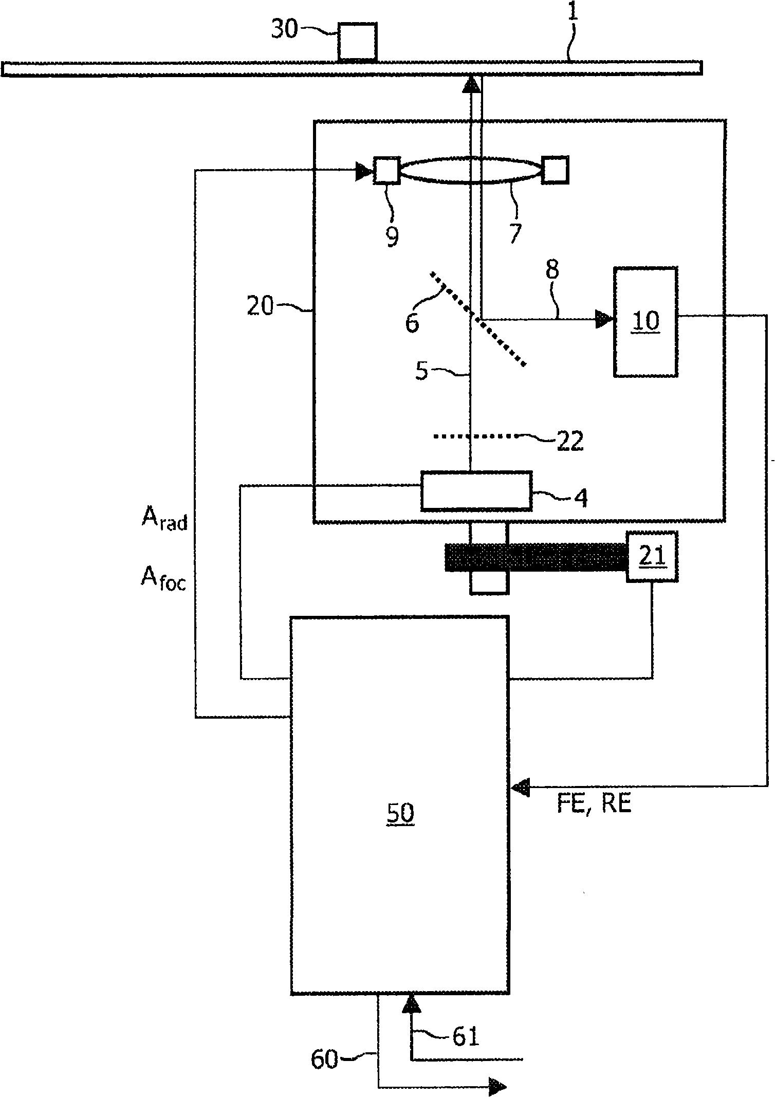
[0047] figure 1 is a schematic block diagram of one embodiment of an optical drive / optical device according to the present invention. The optical carrier 1 is fixed and rotated by a clamping device 30 .

[0048] In one embodiment, the carrier 1 comprises a material suitable for recording information by means of a radiation beam 5 . The recording material may be eg magneto-optical type, phase change type, dye type, metal alloy like copper / silicon or any other suitable material. Information can be recorded on the carrier 1 in the form of optically detectable areas, also called marks for rewritable (RW) media, for writable or write-once-read-many media ( WORM) is called pits.

[0049] In another embodiment, the carrier 1 is of the read-only type, wherein information or data is read from the carrier 1 but it is not possible to record data on the carrier 1 . A carrier 1 of this type may have a read only memory (ROM) format.

[0050] The optical drive / optical device comprises a...


PUM


Abstract

The present invention discloses a method for controlling the position of a radiation beam on an optical carrier (1), e.g. a CD, a DVD, a HD-DVD or a BD disc, in an optical drive. Initially, the optical pickup unit (OPU) is fixated relative to the optical carrier and there is established a closed-loop control, so called capture, in response to an error signal e.g. radial or focus error tracking signal (FE, RE). Then, by servo control means (9, 50) a first bandwidth (BW1) is set in a stabilization period (SP), and subsequently a second bandwidth (BW2) of the servo control means is set. The second bandwidth (BW2) is lower than the first bandwidth (BW1). The invention applies bandwidth switching and thereby provides a more robust operation of the optical drive, as the first and second bandwidths may be separately optimised. Additionally, the power consumption of the optical pickup unit (OPU) may be reduced.

Description

technical field [0001] The invention relates to a method for controlling the position of a radiation beam on an optical carrier, such as a CD, DVD, HD-DVD or BD disc, in an optical drive comprising servo control means. The invention also relates to a corresponding optical drive, a corresponding processing device and a corresponding computer program product. Background technique [0002] In optical drives for recording and reproducing information or data from optical discs, servo systems are used to keep a focused radiation beam, eg a laser beam from an optical pickup unit (OPU), on a desired optical disc track. The servo system allows the laser to precisely follow the tracks on the optical disc to ensure that data is reliably recorded on or read from these tracks. Some known methods of radial control include the push-pull (PP) method for rewritable / recordable optical discs with guide grooves (so-called pre-grooves) and the Differential Phase Detection (DPD) method. [000...

Claims


Application Information

Patent Timeline
IPC IPC(8): G11B7/085G11B7/09
CPCG11B7/0945G11B7/08505G11B7/09
Inventor J·A·威斯S·古森斯
Owner KONINKLIJKE PHILIPS ELECTRONICS NV
Why Eureka
Try Eureka