Guided wave radar level gauge system with grounded probe

Active Publication Date: 2018-10-11
ROSEMOUNT TANK RADAR
View PDF6 Cites 0 Cited by
  • Summary
  • Abstract
  • Description
  • Claims
  • Application Information

AI Technical Summary

Benefits of technology

The present invention allows for a tank to have a radar level gauge installed without needing to modify the tank or have a signal coupling structure enter from the side of the tank's nozzle. This makes installation easier and less expensive. By measuring additional process variables, the accuracy of the filling level measurement can be improved.

Problems solved by technology

Additionally, the probe may unintentionally act as an antenna, picking up signals which may interfere with measurement circuitry connected to the probe if not properly taken care of.

Method used


Image

  • Guided wave radar level gauge system with grounded probe
  • Guided wave radar level gauge system with grounded probe
  • Guided wave radar level gauge system with grounded probe

Examples


Embodiment Construction

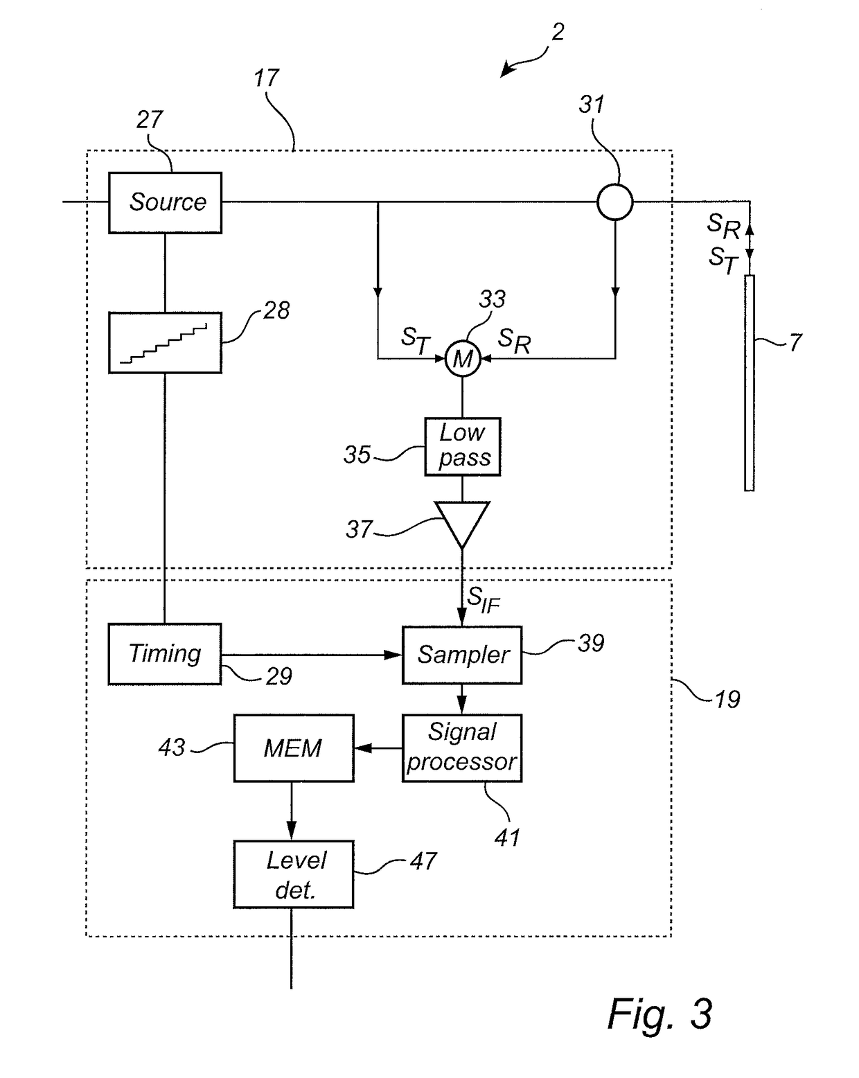
[0074]In the present detailed description, various embodiments of the present invention are mainly discussed with reference to an FMCW-type radar level gauge system.

[0075]It should be noted that this by no means limits the scope of the present invention, which also covers a pulsed radar level gauge system using electromagnetic signals in a suitable frequency range.

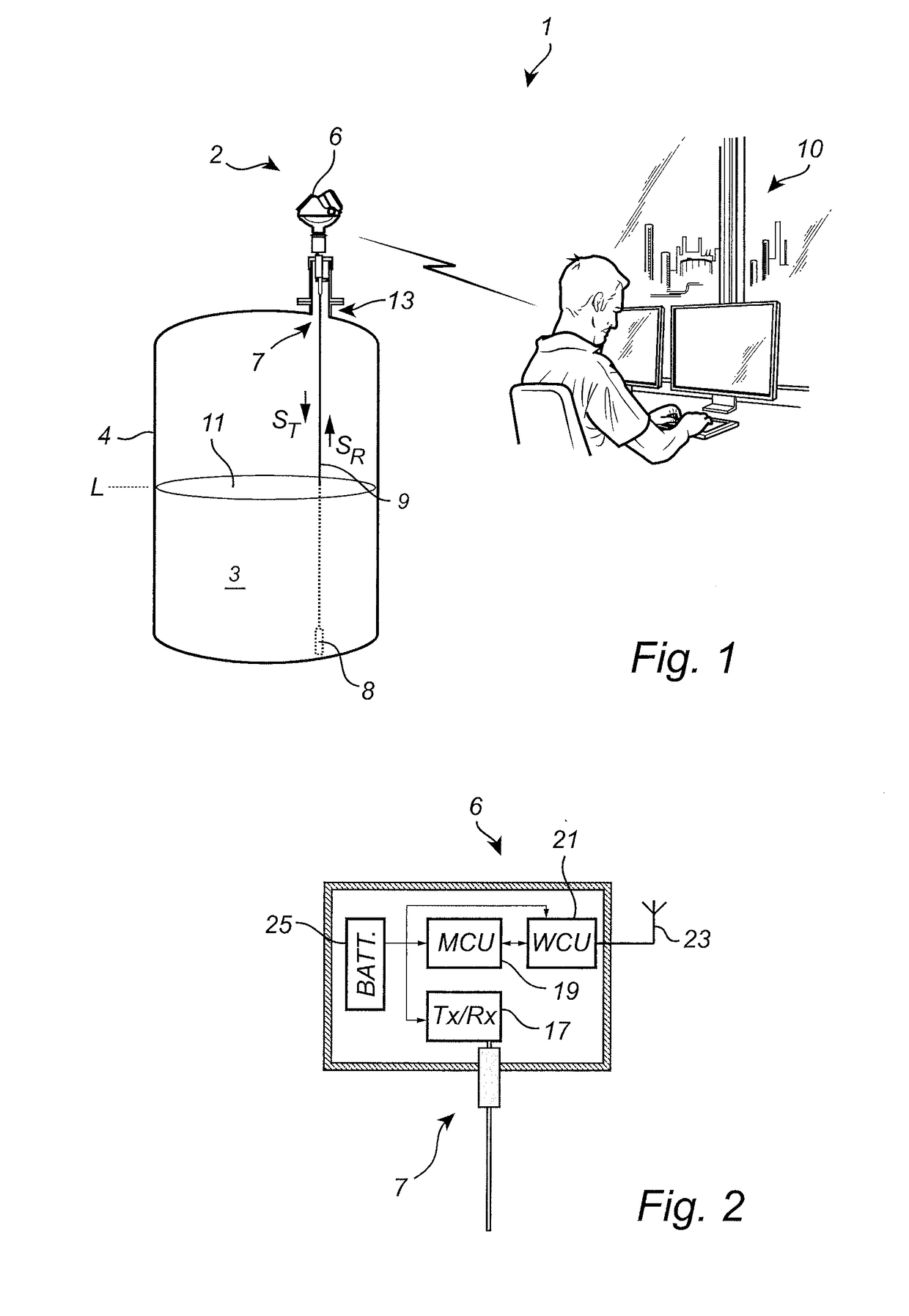
[0076]FIG. 1 schematically shows a level measuring system 1 comprising a radar level gauge system 2 according to an example embodiment of the present invention, and a host system 10 illustrated as a control room.

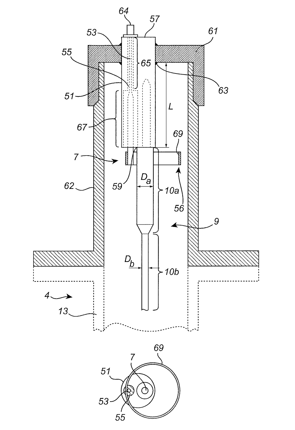
[0077]The radar level gauge system 2 of GWR (Guided Wave Radar) type is installed at a tank 4 having a tubular mounting structure 13 (often referred to as a “nozzle”) extending substantially vertically from the roof of the tank 4.

[0078]The radar level gauge system 2 is installed to measure the filling level of a product 3 in the tank 4. The radar level gauge system 2 comprises a measuring unit 6 and a propagation d...


PUM


Abstract

A radar level gauge system comprising a transceiver; a probe for guiding a transmit signal towards a product in a tank, and for returning a surface echo signal; processing circuitry for determining the filling level based on the transmit signal and the surface echo signal; and a connection arrangement for conductively connecting the probe to the tank, and for providing the transmit signal from the transceiver to the probe. The connection arrangement comprises a feed-through member to which the probe is conductively connected. The feed-through member is in conductive contact with the tank at a grounding position, and a signal conductor extends through the feed-through member from the outside of the tank to the inside of the tank. A tank coupling arrangement is arranged on the inside of the tank to electrically connect the signal conductor and the metallic portion of the tank.

Description

TECHNICAL FIELD OF THE INVENTION[0001]The present invention relates to a guided wave radar level gauge system and to a method of installing a radar level gauge system at a tank.TECHNICAL BACKGROUND[0002]Radar level gauge systems are in wide use for measuring process variables of products, such as filling level, temperature, pressure etc. Radar level gauging is generally performed either by means of non-contact measurement, whereby electromagnetic signals are radiated towards a product in a tank, or by means of contact measurement, often referred to as guided wave radar (GWR), whereby electromagnetic signals are guided towards and into the product by a probe acting as a waveguide. The probe is generally arranged vertically from the top of the tank towards the bottom of the tank. The electromagnetic signals are reflected at the surface of the product, and the reflected signals are received by a receiver or transceiver comprised in the radar level gauge system. Based on the transmitted...

Claims


Application Information

Patent Timeline
IPC IPC(8): G01F23/292G01F23/284G01S13/32G01S7/00G01S13/88
CPCG01F23/2928G01F23/284G01S2007/027G01S7/003G01S13/88G01S13/32G01S13/10G01S13/34G01S7/027
Inventor EDVARDSSON, OLOVFREDRIKSSON, HAKAN
Owner ROSEMOUNT TANK RADAR
Why Eureka
Try Eureka