
Particle detectors

Active Publication Date: 2005-05-03
CARL ZEISS SMT LTD
View PDF2 Cites 8 Cited by
  • Summary
  • Abstract
  • Description
  • Claims
  • Application Information

AI Technical Summary

Benefits of technology

[0016]The selectivity of the detector can be further improved by ensuring that the length of exposed electrode is as short as possible, so that the number of particles incident on part of the electrode other than the tip is minimised.
[0018]The electrode may to advantage be protected by a shield, beyond which the tip region of the electrode extends, the shield preventing particle impacts on the part of the detector other than the exposed tip from interfering with the detector's output.
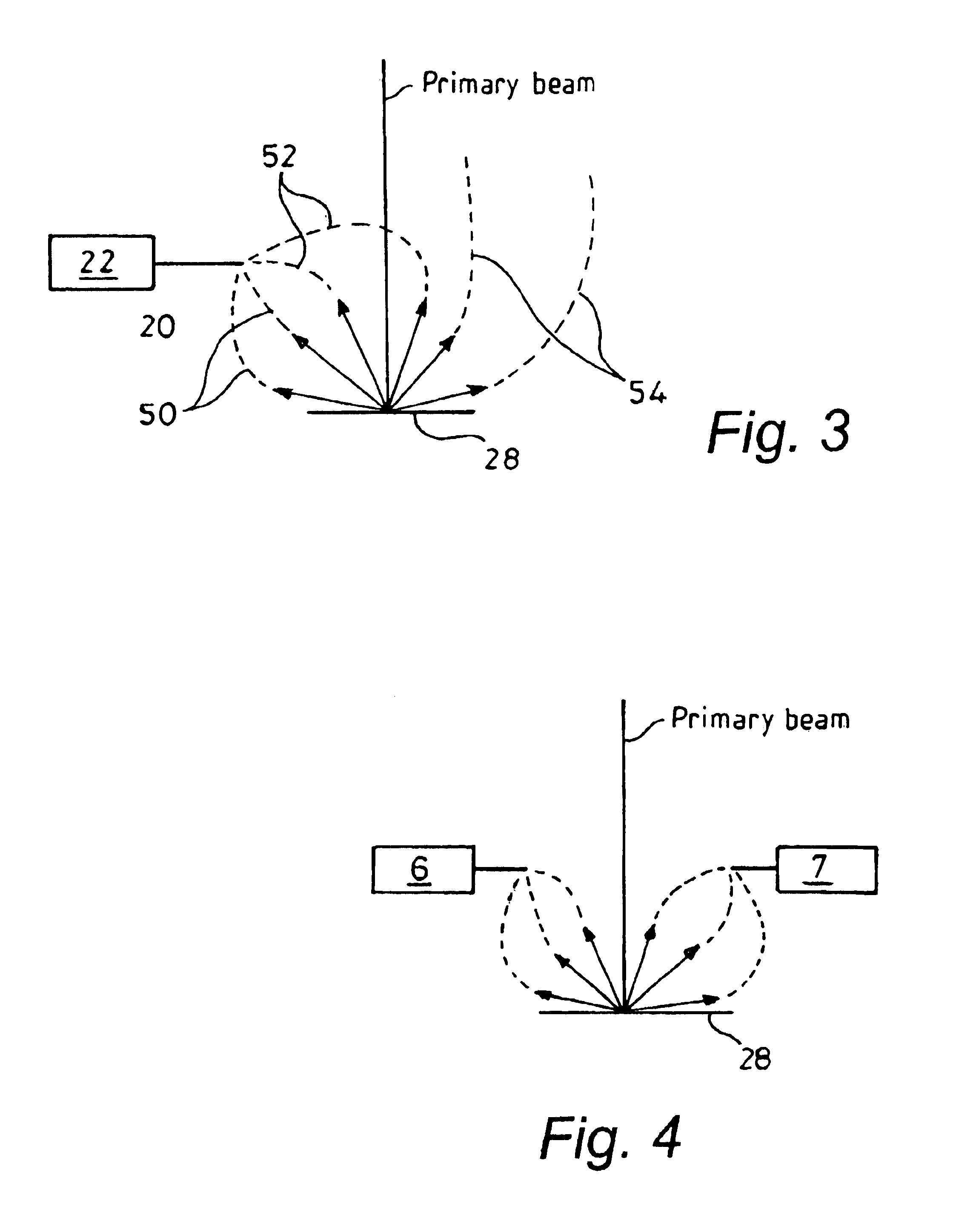
[0024]The detector may to advantage be one of a plurality of such detectors which are angularly spaced from another about the beam axis. This can be used to improve the directionality of the detected signal as well as the signal noise ratio.
[0026]It has been found that this feature improves the bandwidth of the detector. The bandwidth of a detector is limited by stray capacitance. Any electronic components, surfaces and wires have a capacitance. Fast frequencies are led away via these ‘stray capacitors’ and therefore not amplified which makes the image captured using the detector appear smeared. An increased length of wire increases its capacitance yielding a lower bandwidth. Therefore locating PCB as close to the electrode as possible reduces stray capacitance, and thus increases bandwidth.

Problems solved by technology

Thus, if secondary electrons are to be detected in an electron microscope, the detector may be so positioned that secondary electrons travelling from the sample into the zone are likely to collide with gaseous atoms in the zone, thereby generating a cascade of collisions.

Method used


Image

  • Particle detectors
  • Particle detectors
  • Particle detectors

Examples


Embodiment Construction

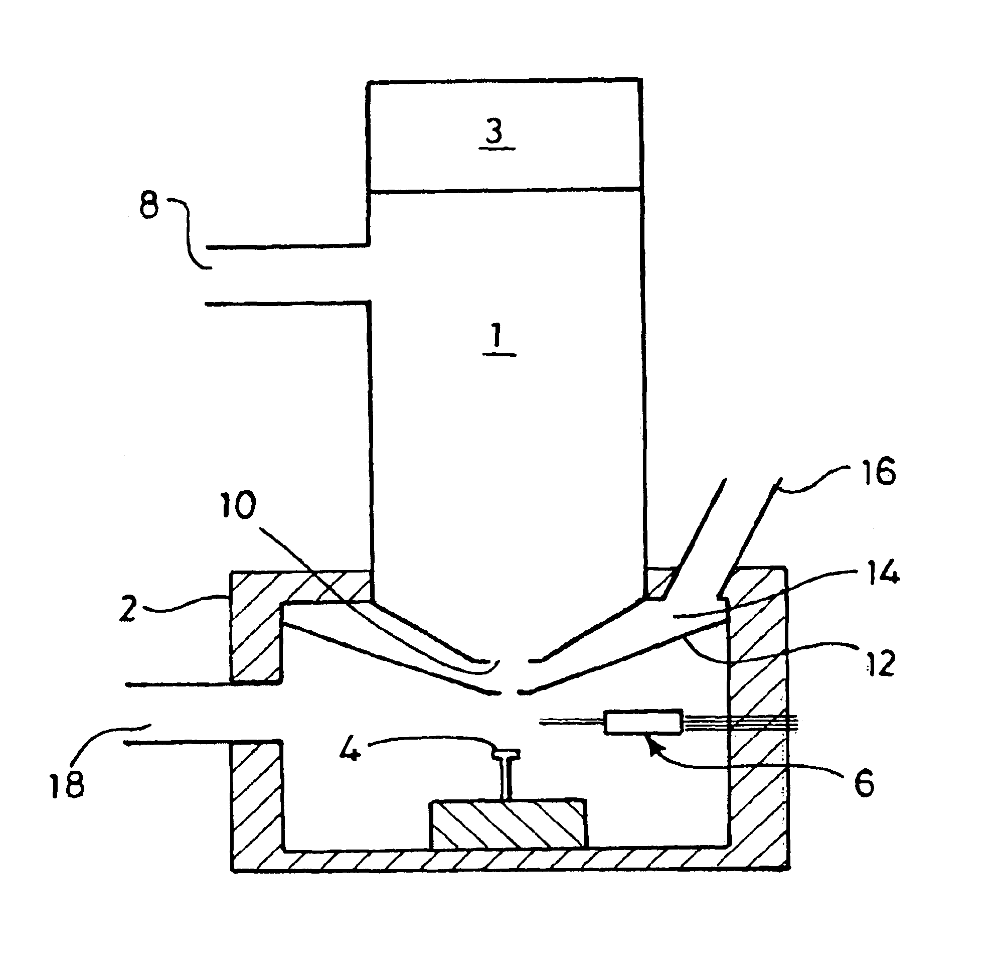
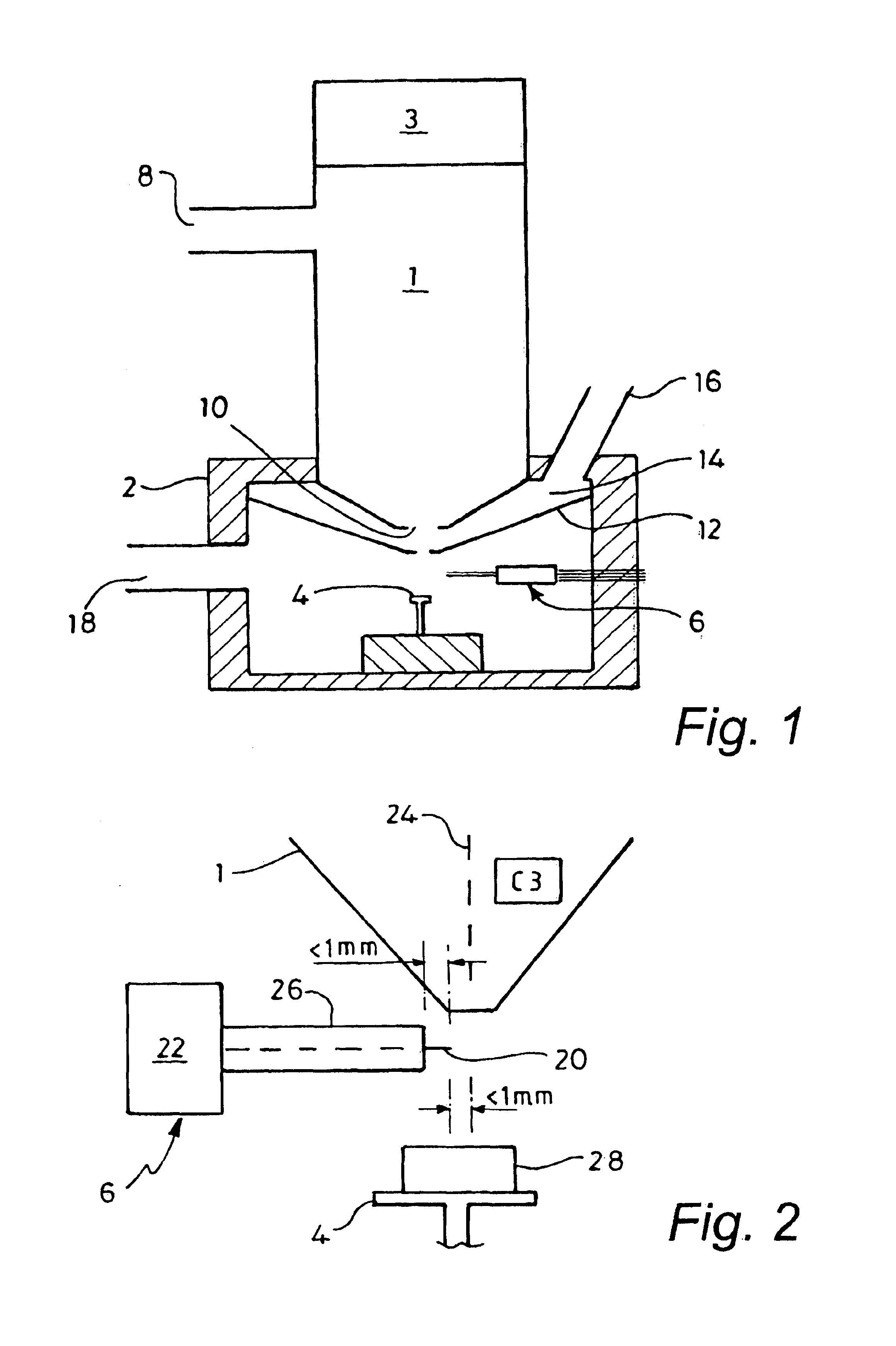
[0037]With reference to FIG. 1, an electron microscope in accordance with the invention comprises an electron column 1 mounted on a sample chamber 2 which contains a platform support 4 for a specimen in registry with the column 1. The chamber also contains a secondary electron detector 6 for detesting secondary electrons emanating from a sample on the platform 4. At the top of the column 1 there is provided an electron gun 3 for providing electrons for the column 1.

[0038]The gun 3 and electron column 1 are identical to the gun and electron column of the electron microscope described in PCT Publication No. WO 98 / 22971, the relevant subject matter of which is therefore incorporated herein by reference.

[0039]Thus, the column 1 includes a vacuum port 8 connected to a pump (not shown) for maintaining a vacuum in the column 1.

[0040]The top of the chamber 2 has an opening through which the bottom portion of the column 1 extends. The column 1 is a tight fit within the opening in the chamber...


PUM


Abstract

A signal detector for detecting electrically charged particles in a gaseous medium has an electrode having a tip region for gathering charged particles. The electrode is connected to a voltage source for applying a voltage that generates electro-static field for attracting the particles to the electrode, and at least part of the tip region has a radius of curvature which is sufficiently small or (in the case of a point tip or sharp edge) infinitesimally small so as to create a localised high intensity electro-static field which defines a detection zone in which, in use, charge particles are accelerated by the electric field so as to ionise gas molecules in the zone and thus amplify the signal to be received by the detector. The received signal is supplied through an output of the detector. The detector may be provided in a sample chamber of a scanning electron microscope.

Description

FIELD OF THE INVENTION[0001]This invention relates to a signal detector for detecting electrically charged particles in gaseous medium, a sample chamber for holding a sample in such a medium, a scanning beam imaging device, such as an electron microscope and to a method of achieving gas amplification of a secondary electron signal.BACKGROUND TO THE INVENTION[0002]In early types of electron microscope, the sample to be imaged was contained in a sample chamber in which a vacuum was maintained during the imaging process. However, there are occasions on which it is necessary or desirable to image specimens in a gaseous environment in a scanning electron microscope. For example the gaseous environment would inhibit the evaporation of moisture from a biological specimen, and can dissipate surface charges from non-conductive specimens, which charges would otherwise accumulate to the detriment of image resolution.[0003]The use of a gaseous environment amplify a secondary electron signal obt...

Claims


Application Information

Patent Timeline
IPC IPC(8): G21K1/00H01J37/244G21K7/00
CPCH01J37/244H01J2237/2608H01J2237/2449H01J2237/2448
Inventor HAYN, ARMIN HEINZ
Owner CARL ZEISS SMT LTD
Learn More