Electrical Connector, Wire Harness, and Method for Arranging Wire Harness

a technology of wire harnesses and wire connectors, applied in the direction of fixed connections, securing/insulating coupling contact members, coupling device connections, etc., can solve the problems of troublesome wire harness arrangement, increased cost, complicated manufacturing, etc., and achieve low cost, high degree of freedom, and high degree of freedom

Inactive Publication Date: 2006-10-12
TYCO ELECTRONICS JAPAN GK
View PDF2 Cites 21 Cited by
  • Summary
  • Abstract
  • Description
  • Claims
  • Application Information

AI Technical Summary

Benefits of technology

[0018] Accordingly, the present invention was devised in light of the problems described above. It is an object of the present invention to provide an electrical connector connected to a flat cable, a wire harness, and a method for arranging a wire harness in which arranging the wire harness is simple and easy, the cost is low, and the degree of freedom in the housing construction is high.

Problems solved by technology

Therefore, there is a problem in that arranging the wire harness becomes troublesome.
However, since thin parts that link adjacent base housings are present, the degree of freedom in the housing construction is low, and a new mold for molding base housings is required in such cases, so that manufacturing is complicated, and there is a concern of increased cost.

Method used


Image

  • Electrical Connector, Wire Harness, and Method for Arranging Wire Harness
  • Electrical Connector, Wire Harness, and Method for Arranging Wire Harness
  • Electrical Connector, Wire Harness, and Method for Arranging Wire Harness

Examples


Embodiment Construction

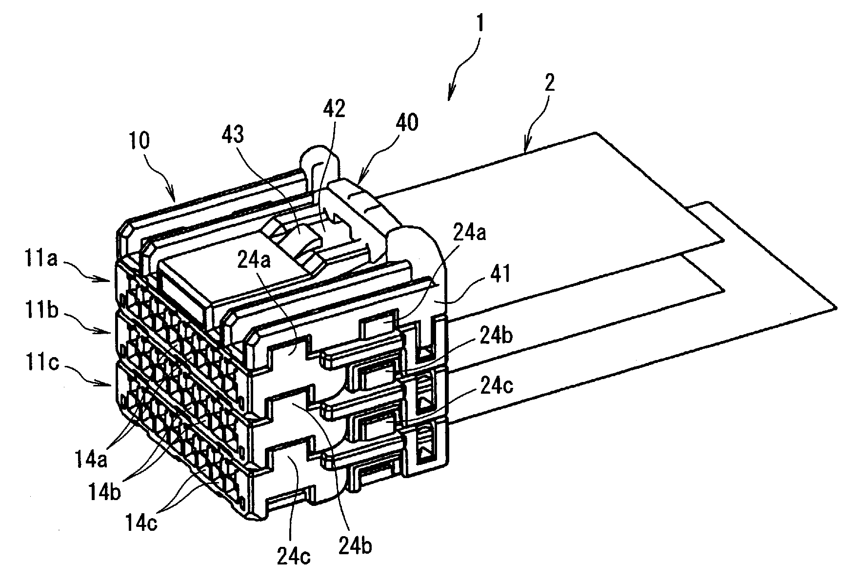
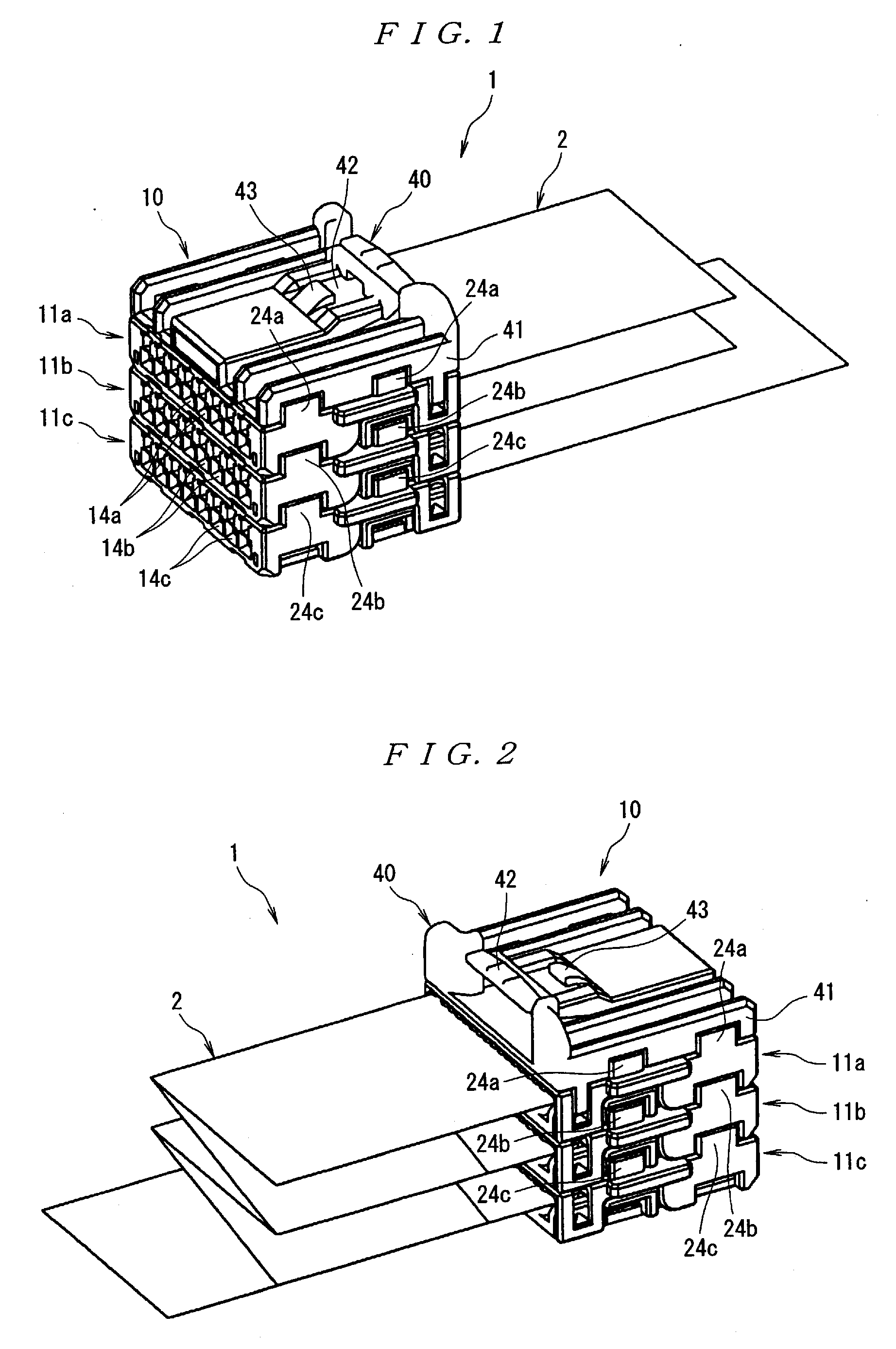
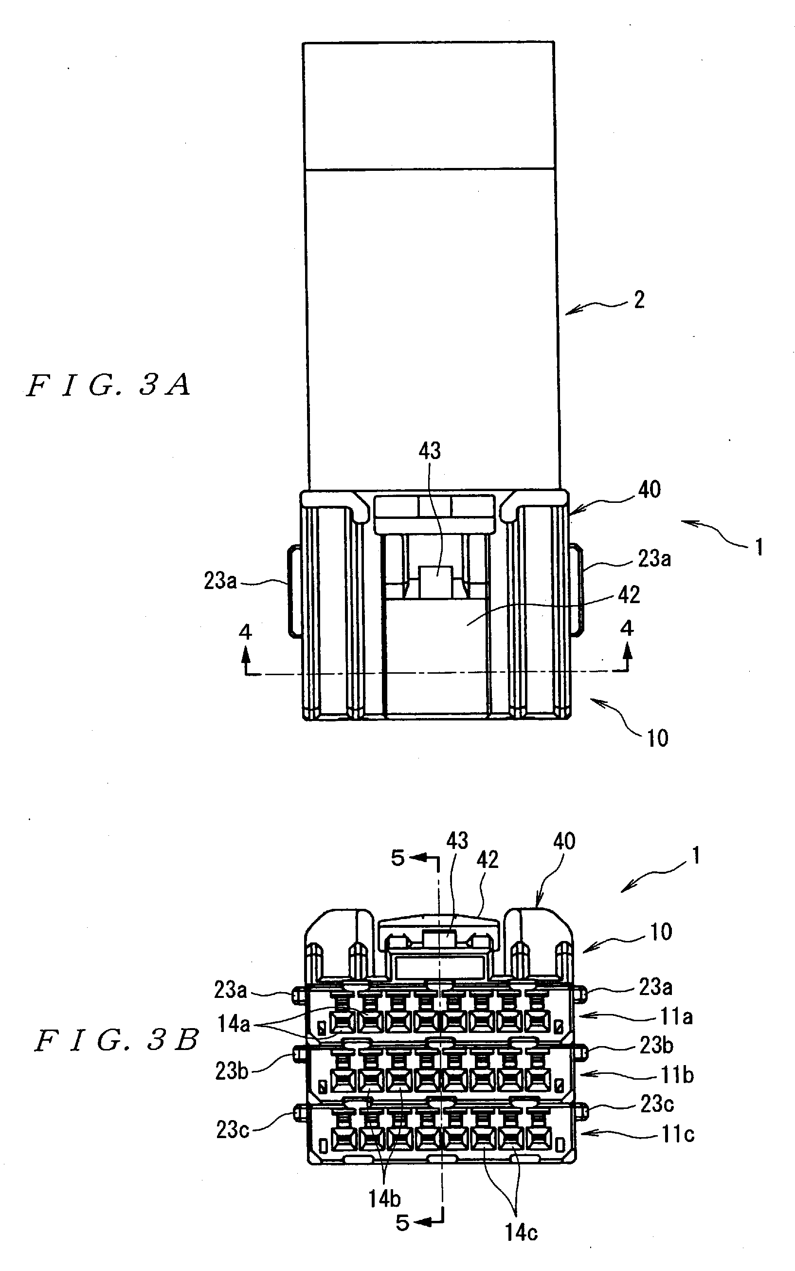
[0035] Next, an embodiment of the present invention will be described with reference to the figures. Referring to FIGS. 1 through 5, the wire harness 1 is formed by connecting an electrical connector 10 to one end of a flexible circuit board (FPC) 2. Here, as is shown in FIG. 6, for example, a FPC 2 is used which has a plurality of conductor patterns 2a on one surface thereof, and which comprises three first terminal sections 3 on one end, five second terminal sections 4 on the other end, and one first terminal section 3 and two second terminal sections 4 substantially in the central portion.

[0036] Here, the electrical connector 10 comprises mutually stackable upper-stage, middle-stage, and lower-stage base housings 11a, 11b, and 11c that have the same shape, and a lock housing 40. Although the electrical connector 10 is not limited to a connector comprising upper-stage, middle-stage, and lower-stage base housings 11a, 11b, and 11c, i.e., three stages of base housings, a case in wh...


PUM


Abstract

An electrical connector connected to a flat cable, a wire harness, and a method for arranging wire harness is disclosed. Arranging the wire harness is easy and simple, the cost is low, and the degree of freedom in the housing construction is high. The electrical connector 10 has a plurality of mutually stackable base housings 11a, 11b, and 11c having the same shape, with each of these base housings 11a, 11b, and 11c having contact receiving cavities 16a, 16b, and 16c in a single row. At least one lock housing 40 is attached to the uppermost and / or lowermost base housing of the plurality of stacked base housings 11a, 11b, and 11c. A plurality of contacts 30a, 30b, and 30c are connected to the flat cable 2 and are inserted in the contact receiving cavities 16a, 16b, and 16c.

Description

FIELD OF THE INVENTION [0001] The present invention relates to an electrical connector and more particularly to an electrical connector for a flat cable, a wire harness, and a method for arranging the wire harness. BACKGROUND OF THE INVENTION [0002] Wire harnesses in which electrical connectors are connected to flat cables, including flexible circuit boards (FPC), have been used in the past mainly in electronic devices such as personal computers. In recent years, however, there has been an increasing demand for the use of such wire harnesses for the connection to controllers in the automotive field or the like. [0003] For example, wire harnesses in which electrical connectors are connected to flat cables are used for the connection to automotive transmission controllers. In such cases, installation involves pulling an electrical connector connected to the end portion of a flat cable out of an opening in the transmission case. [0004] In such cases, when a multipole connector in which...

Claims


Application Information

Patent Timeline
Patent Type & Authority Applications(United States)
IPC IPC(8): H01R13/58
CPCH01R13/506H01R13/514H01R12/59H01R43/28H01R2201/26H01R13/5829
Inventor KOMIYAMA, RYUICHI
Owner TYCO ELECTRONICS JAPAN GK
Why Eureka
Try Eureka