Torque control apparatus and vehicle control system having the same

a technology of torque control and control apparatus, which is applied in the direction of electrical control, process and machine control, instruments, etc., can solve the problems of inability to achieve the torque demand, the inability to accurately compute the torque loss, and the change in the combustion state of the engine with time, so as to improve the torque control of the internal combustion engin

Inactive Publication Date: 2006-10-12
DENSO CORP
View PDF6 Cites 12 Cited by
  • Summary
  • Abstract
  • Description
  • Claims
  • Application Information

AI Technical Summary

Benefits of technology

[0008] The present invention addresses the above disadvantages. Thus, it is an objective of the present invention to provide a torque control apparatus, which achieves improved torque control of an internal combustion engine. It is another objective of the present invention to provide an engine control system having such a torque control apparatus.
[0009] To achieve the objectives of the present invention, there is provided a torque control apparatus for an internal combustion engine. The torque control apparatus includes a combustion stop means, a combustion period torque loss computing means, a combustion stop period torque loss computing means and a torque control means. The combustion stop means is for stopping fuel combustion of the engine when a combustion stop condition is satisfied. The combustion period torque loss computing means is for computing a torque loss of the engine in a combustion period, in which the fuel combustion of the engine takes place. The combustion period torque loss computing means computes the torque loss of the engine based on an operational state of the engine in the combustion period. The combustion stop period torque loss computing means is for computing a torque loss of the engine in a combustion stop period, in which the fuel combustion of the engine is stopped by the combustion stop means. The combustion stop period torque loss computing means computes the torque loss of the engine in the combustion stop period based on the torque loss of the engine in the combustion period and a state of the combustion stop implemented by the combustion stop means. The torque control means is for controlling a torque generated from the engine based on a torque demand, which is demanded by an operator, and a selected one of the torque loss in the combustion period and the torque loss in the combustion stop period. In the combustion period, the torque control means uses the torque loss computed by the combustion period torque loss computing means as the selected one of the torque losses. In the combustion stop period, the torque control means us

Problems solved by technology

However, the combustion state of the engine changes with time.
In such a case, the torque loss cannot be accurately computed, and thereby a torque demand, which is demanded by a driver, cannot be achieved.
In this torque based control system, when the torque demand cannot be met in the engine, a torque balance relative to the other

Method used


Image

  • Torque control apparatus and vehicle control system having the same
  • Torque control apparatus and vehicle control system having the same
  • Torque control apparatus and vehicle control system having the same

Examples


first embodiment

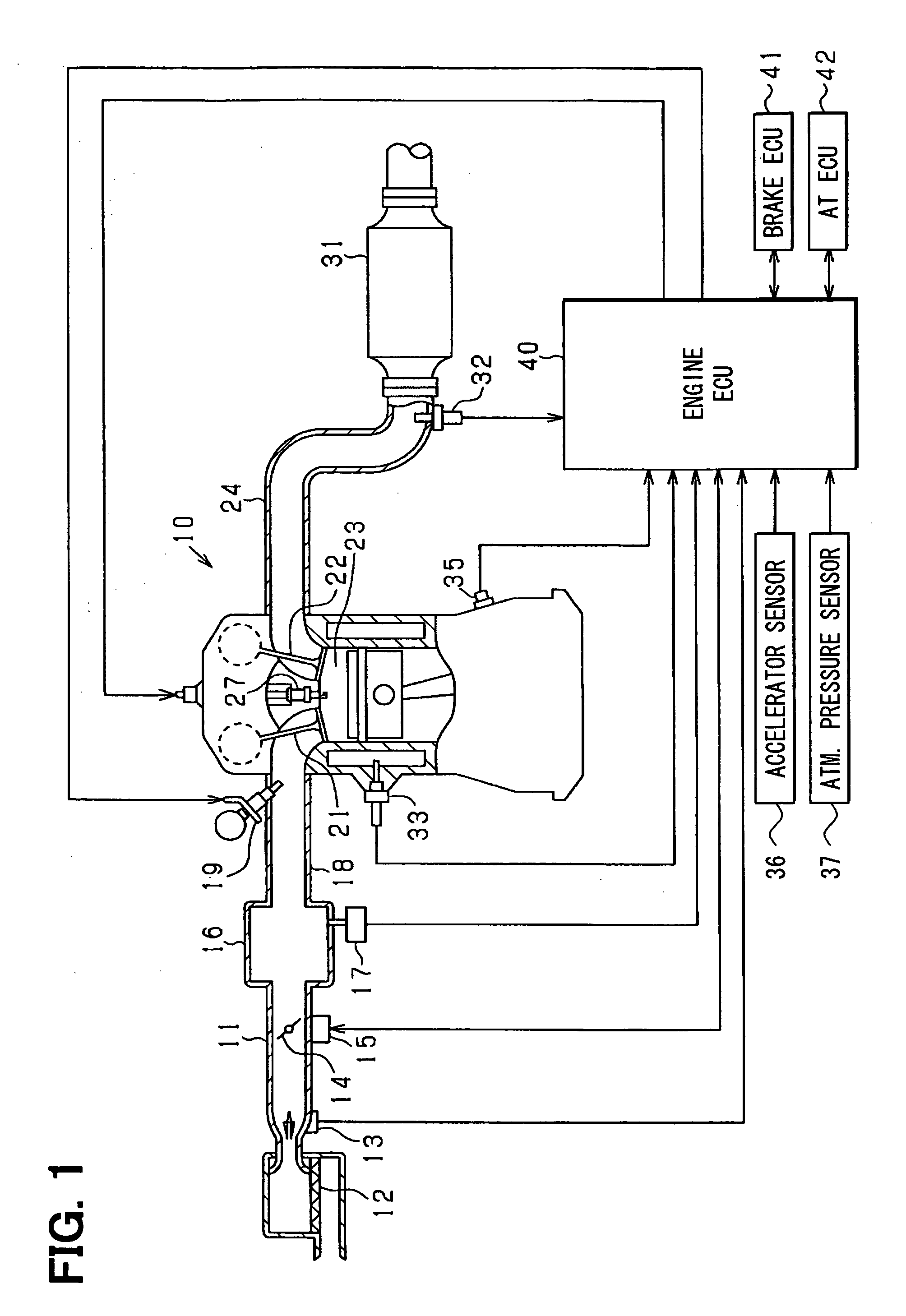
[0033] A first embodiment of the present invention will be described with reference to the accompanying drawings. In the present embodiment, an electronic control unit (hereinafter, referred to as “ECU”) acts as a core unit of an engine control system (constituting a part of a vehicle control system) that controls an in-vehicle multi-cylinder gasoline engine (serving as an internal combustion engine), more specifically, for example, a fuel injection quantity and ignition timing of the engine. First, an entire structure of the engine control system will be described with reference to FIG. 1.

[0034] In the engine 10 of FIG. 1, an air cleaner 12 is provided in an upstream end of an intake air pipe 11. An airflow meter 13 is provided on a downstream side of the air cleaner 12 to measure an intake air quantity (a throttle passing air quantity). A throttle valve 14 is provided on a downstream side of the airflow meter 13. An opening degree of the throttle valve 14 is adjusted by a throttl...

second embodiment

[0065] Next, a second embodiment will be described while focusing on differences between the second embodiment and the first embodiment. In the present embodiment, there is implemented a control operation, in which the number of cylinders, i.e., the quantity of cylinders under the fuel cut (hereinafter, referred to as “F / C cylinder quantity” or alternatively “combustion stop mode cylinder quantity”) is variably set. That is, the engine is operated with the reduced number of cylinders, i.e., the reduced quantity of cylinders. Here, the correction of the engine torque loss is performed based on the F / C cylinder quantity. The F / C cylinder quantity may be computed according to a deviation between the estimative indicated torque and the indicated torque demand (=the estimative indicated torque−the indicated torque demand). Specifically, the F / C cylinder quantity is computed based on a quotient, which is obtained by dividing the torque deviation (=the estimative indicated torque−the indic...

third embodiment

[0072] Next, a third embodiment will be described while focusing on differences between the third embodiment and the first embodiment. In the present embodiment, the engine torque loss in the combustion period and the engine torque loss in the fuel cut-off period are individually computed, and one of these torque losses is selectively used to compute the current engine torque loss.

[0073]FIG. 12 is a block diagram showing an engine torque loss computing section 52 of the present embodiment. In the structure shown in FIG. 12, a first torque loss computing section 81 for computing the engine torque loss in the combustion period and a second torque loss computing section 82 for computing the engine torque loss in the fuel cut-off period are provided.

[0074] Here, the first torque loss computing section 81 and the second torque loss computing section 82 respectively use different characteristics to compute the pump torque loss and the frictional torque loss. FIG. 13A shows the pump loss...


PUM


Abstract

In an engine torque loss computing section, a pump loss computing section computes a pump torque loss, and a frictional loss computing section computes a frictional torque loss. The pump torque loss and the frictional torque loss are summed to obtain an engine torque loss. Furthermore, a torque loss correction amount computing section computes a torque loss correction amount, and a correction amount changing section changes the torque loss correction amount based on a result of determination of whether fuel cut-off is currently executed. The torque loss correction amount is added to the uncorrected initial engine torque loss to obtain a corrected engine torque loss.

Description

CROSS REFERENCE TO RELATED APPLICATION [0001] This application is based on and incorporates herein by reference Japanese Patent Application No. 2005-112387 filed on Apr. 8, 2005. BACKGROUND OF THE INVENTION [0002] 1. Field of the Invention [0003] The present invention relates to a torque control apparatus and a vehicle control system having the same. [0004] 2. Description of Related Art [0005] In a previously proposed control system of an internal combustion engine of a vehicle, a torque demand (also referred to as a demanded torque) is computed based on an operational amount (an accelerator operational amount or alternatively referred to as an opening degree) of an accelerator operated by a driver, and then actuators of the engine are operated to achieve this torque demand. For example, according to Japanese Unexamined Patent Publication No. 11-50889, a target shaft torque of an engine is computed based on an accelerator operational amount and an engine rotational speed, and a comb...

Claims


Application Information

Patent Timeline
IPC IPC(8): B60W10/06B60W10/18F02D41/12F02D41/04F02D45/00
CPCB60W10/06B60W10/18B60W2510/0657Y10T477/814F02D41/123F02D41/2451F02D2200/1006F02D11/105
Inventor ICHIHARA, HIDEAKI
Owner DENSO CORP
Why Eureka
Try Eureka